
Hello, I Just bought the Baby Orangutan B-328, I didn’t realize that 2 of the timers, and 4 of the PWM outputs were taken up by the dual H-bridge. Is there a way to disable the dual H-bridge motor controller, so that I can gain access to the timers and PWM outputs on PD5, PD6, PD3, and PB3? If this is possible, is it reversible so that I can regain access to the dual H-bridge? The reason I need to disable the dual H-bridge is because I am trying to learn programming in the Arduino environment. I need all the PWM outputs to make it comparable to the UNO. Don’t get me wrong, I love this little guy. I am just starting out with all of this and not having those PWM outputs is making it more difficult. I realize now that I should have just bought an Arduino UNO. Maybe that will be my next purchase from your website. Many thanks in advance.
Hello.
As long as you leave the motor driver outputs disconnected, you don’t need to disable the motor drivers to free up those AVR PWM outputs. However, with the exception of PB3, which is available via the programming header, those pins are not broken out on the Baby Orangutan, so accessing them is fairly difficult, especially if you are new to working with boards like this. I can show you where you might consider accessing them, but I recommend against it unless you are quite comfortable with surface-mount soldering.
If you don’t mind my asking, what do you want to use those additional PWM outputs for? It’s possible I can help you accomplish the same thing using our Pololu AVR libraries.
- Ben
Well, I am new to all of this… OK the reason I need those PWM outputs is because of the sample code at the bottom of this pagehttp://docs.macetech.com/doku.php/shiftbrite. I cant seem to get it to run on my Baby O. I have the header map for the Baby O, in Arduino except those pins are only labeled as M1A, M1B, M2A, and M2B. I didn’t know if they were accessible via the Arduino environment. There are other example codes on the Arduino site that need more than two PWM outputs and more than one timer.
The code on that page doesn’t use those pins as PWM outputs, and it doesn’t use those timers. It is just using them as standard digital outputs, which the Baby Orangutan has plenty of. All you need to do to make the Baby Orangutan work with your ShiftBrite is change the pin definitions at the top of the program and change your connections accordingly (although I’m not sure if there will be any timing issues due to the fact that the Baby Orangutan runs at 20 MHz and the Arduino runs at 16 MHz; I think it will be ok, but if not, you might need to tweak the lengths of the delays in that program). For example:
#define clockpin 2 // CI = PD2
#define enablepin 4 // EI = PD4
#define latchpin 7 // LI = PD7
#define datapin 8 // DI = PB0
However, note that we have example code for controlling ShiftBrites with our Orangutans at the bottom of our ShiftBrite product pages:
pololu.com/catalog/product/1222
You are free to use the motor driver timers any way you want on the Baby Orangutan. The only thing you don’t have is access to three of the four Timer 0 and Timer 2 PWM outputs, but I think that will not prove to be much of a limitation, especially since you can fairly easy generate PWMs in software using interrupts. For example, the Pololu AVR library does this to allow you to control up to 16 servos simultaneously. I suggest you take a look at the Pololu AVR Library and all of the example programs we have for that.
- Ben
Yes I have ran the sample code on the ShiftBrite page and it works like a charm. It’s just so confusing to me. When I say that I am new, I mean I am new new  . I have never written any code, nor have I ever messed with microcontrollers. I will try the new pin definitions you suggested and report back.
Ok I tried the Arduino sketch and got nothing (note: I only have one ShiftBrite. Might that have something to do with it not working?). Reassigned the pins for the AVR studio code that you have on the ShiftBrite page and compiled it loaded the .Hex and it worked perfectly. So I know I didn’t fry my ShiftBrite. I guess I need to try and modify the Arduino Sketch for one ShiftBrite and see if that is what is going on.
Well, the fact that you’ve already gotten programs doing something makes it seem like you might be a quick learner. Please let me know if you get into any trouble, or if there are any other Arduino sketches you want to try to adapt to work on the Baby Orangutan. Ultimately, you might end up wanting to go with an Arduino for learning purposes because there are more beginner resources available out there.
- Ben
Yeah I am thinking that the Arduino Uno is what I should have bought. However, I am enjoying my Baby Orangutan. It is fun to play with. Maybe me not knowing anything and trying to figure out what is happening in the Arduino Sketch will help me figure this thing out even faster. I will keep trying. Just so you know I am telling everyone about your company via YouTube, Google+, and Facebook. Keep up the great work! I will be stocking up on more supplies from Pololu.com. I am glad to see that y’all work closely with SparkFun. That is another great company. Thanks again for all your help! ![]()
I am getting uber-frustrated! All I want to do is make one ShiftBrite module light up using the Arduino sketch located right here. It doesn’t have to be that sketch exactly, anything close would suffice. ![]() I can not get this sketch to work.
I can not get this sketch to work.
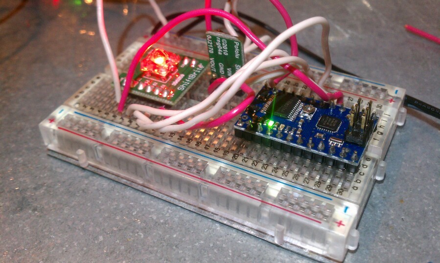
OK here is my pin layout.
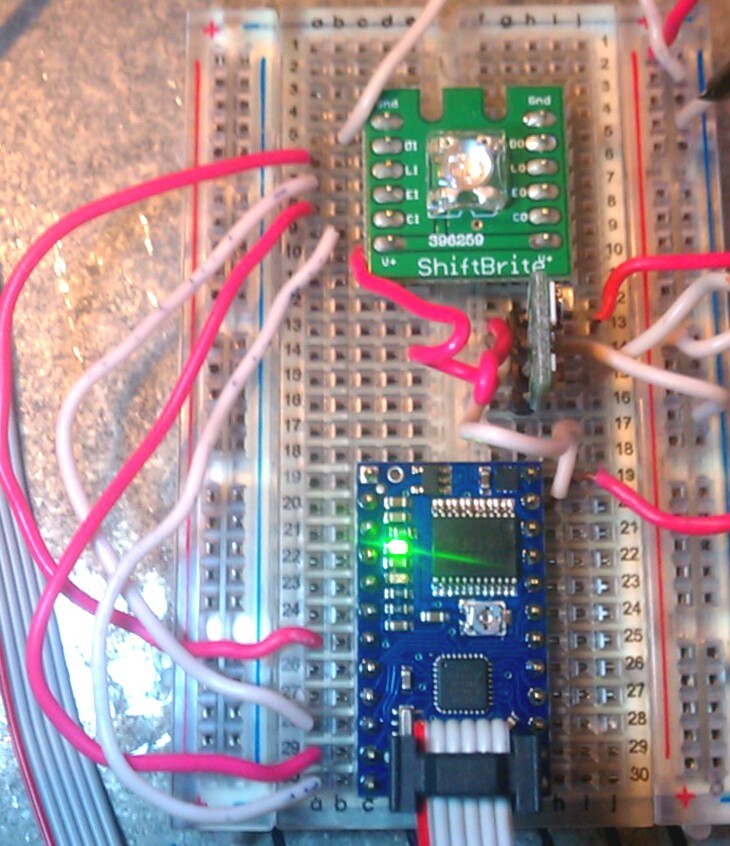
I know one of the wires was out of place in this particular photo. It has been fixed.
#define clockpin 7 // CI = PD7
#define enablepin 4 // EI = PD4
#define latchpin 2 // LI = PD2
#define datapin 0 // DI = PD0
What I want is to be able to light up the ShiftBrite. Thats it.
I do not understand this line of code -
SPCR = (1<<SPE)|(1<<MSTR)|(0<<SPR1)|(0<<SPR0);
I cant figure out this section of code either -
SPDR = SB_CommandMode << 6 | SB_BlueCommand>>4;
while(!(SPSR & (1<<SPIF)));
SPDR = SB_BlueCommand<<4 | SB_RedCommand>>6;
while(!(SPSR & (1<<SPIF)));
SPDR = SB_RedCommand << 2 | SB_GreenCommand>>8;
while(!(SPSR & (1<<SPIF)));
SPDR = SB_GreenCommand;
while(!(SPSR & (1<<SPIF)));
Could someone please explain this and maybe show me what I need to do to make the code run on my Baby O. Thanks for any help on this subject.
Shoot, I’m sorry, it looks like I didn’t look at that code closely enough, and I was thrown by your initial statement that you needed to use the PWM lines so I didn’t look carefully at what lines were being used by default in that sketch. Those lines are not PWM outputs, they are SPI pins, and that sketch using the AVR’s SPI hardware module to send data to the ShiftBrite. Basically, I have some good news and some bad news: the SPI pins are available on the Baby Orangutan, but they are also the pins used for programming the Baby Orangutan, so connecting a ShiftBrite to them could interfere with your ability to reprogram the board. If you want to use that sketch, you would have to disconnect the ShiftBrite from the BabyOrangutan every time you want to program it. If you want to proceed with this, I can tell you what to do.
However, I think in this case you would be better off using the code on our ShiftBrite page to control your ShiftBrite. Note that you don’t have to understand how those functions work or what they’re doing; you can just treat them as mysterious library functions that you call to get the colors you want. The part you should understand is what main() is doing, and I can help you with that if you want.
- Ben
Yes, any help would be awesome  .
.
I don’t mind connecting and disconnecting the ShiftBrite every time. I have a second breadboard that I could put the ShiftBrite on to make disconnecting it easier.
Yeah I know I kinda strayed from the original topic  sorry. There are other sketches that require more than two PWM outputs and I just needed to know if those were available for use without using the dual H-bridge motor controller.
The code that is on your page confuses me even futher  . lol. Arduino seem a little more friendly to n00bs. For instance the ShiftBrite code, I can “read” it a little better in Arduino, than the code in AVR studio 4.
thanks.