Hello. I have a platform that uses both a DV24V22F5 and a DV24V50F5 step down regulator to drop a common 12V input down to two separate 5V rails. I have a single 5V arduino digital output controlling the enable pins on each regulator.
By default, I want the regulators to start up in disable mode. Normally, I could just use a pull-down resistor to do this while the arduino digital output floats during initial boot. However, the regulators have an internal 100K pull-up resistor that is basically overpowering the 10K pull-down i’ve added.
I did the math and I’d need at least a 1.9M Ohm pull-down to overpower the regulator’s internal 100K pull-up resistor (@ 12V Vin) and drive the enable pin below 0.6V (as required in documentation). Rather than doing this, I was wondering if there is a way to disable/remove the pull-up resistor.
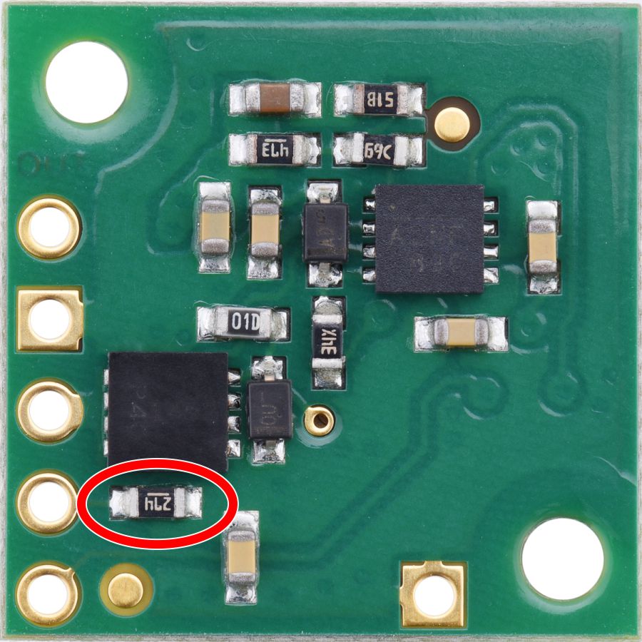
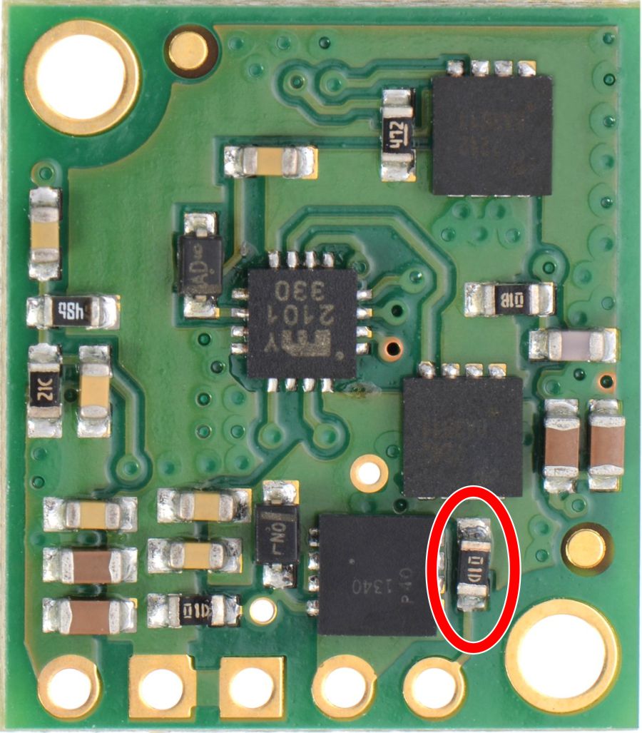
So, is there a way to disable the pull-up? If not, can I just cut the trace from the pull-up resistor to Vin? Can I remove the resistor entirely? Can anybody point me to which resistor on the boards is the pull-up?
Thanks so much!