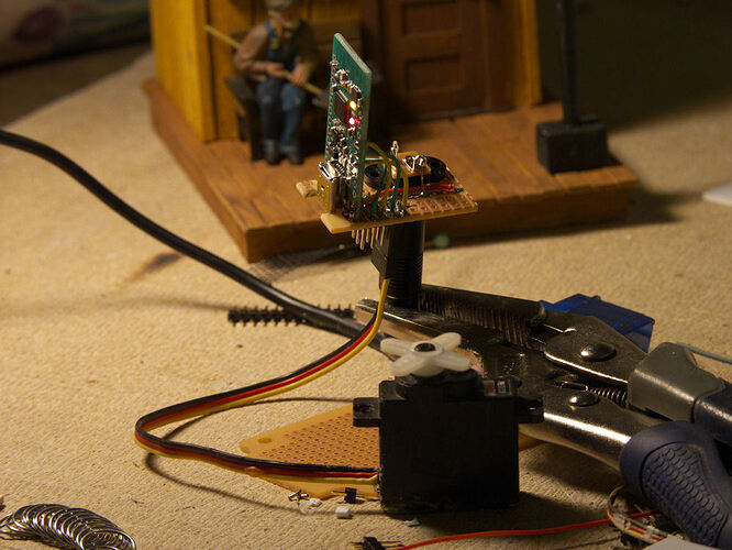
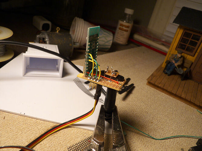
I’ve had great success with my master/slave setup and now I want to do a short run of breakout boards for the wixel. I’ve designed a small board that will allow access to the servo outputs, P0_2, P0_3, P0_4, P1_0, P1_1 and P1_2. That is enough for my current application but was wondering about some of the sections I have not worked with, the three remaining analog inputs, P0_0, P0_1 and P0_5. I also have room for two more, no need to waste real estate. I was thinking P1_6 and P1_7 so I can get to the TX/RX for a possible serial connection later or just use them for generic I/O. Does this sound reasonable? I’m using the standard servo and USB libraries- are there any conflicts with these ports using those?
Also, one other question. I’d like to mount the wixel ‘standing up’ so the servo connect pins are on the bottom and the wixel stands up. Sort of an ‘L’ shape where the wixel is up and down and the breakout board is on the bottom. I know I’ve seen ‘right angle’ headers that would do this, but I can’t seem to find any. Anyone know where I can get some?


