
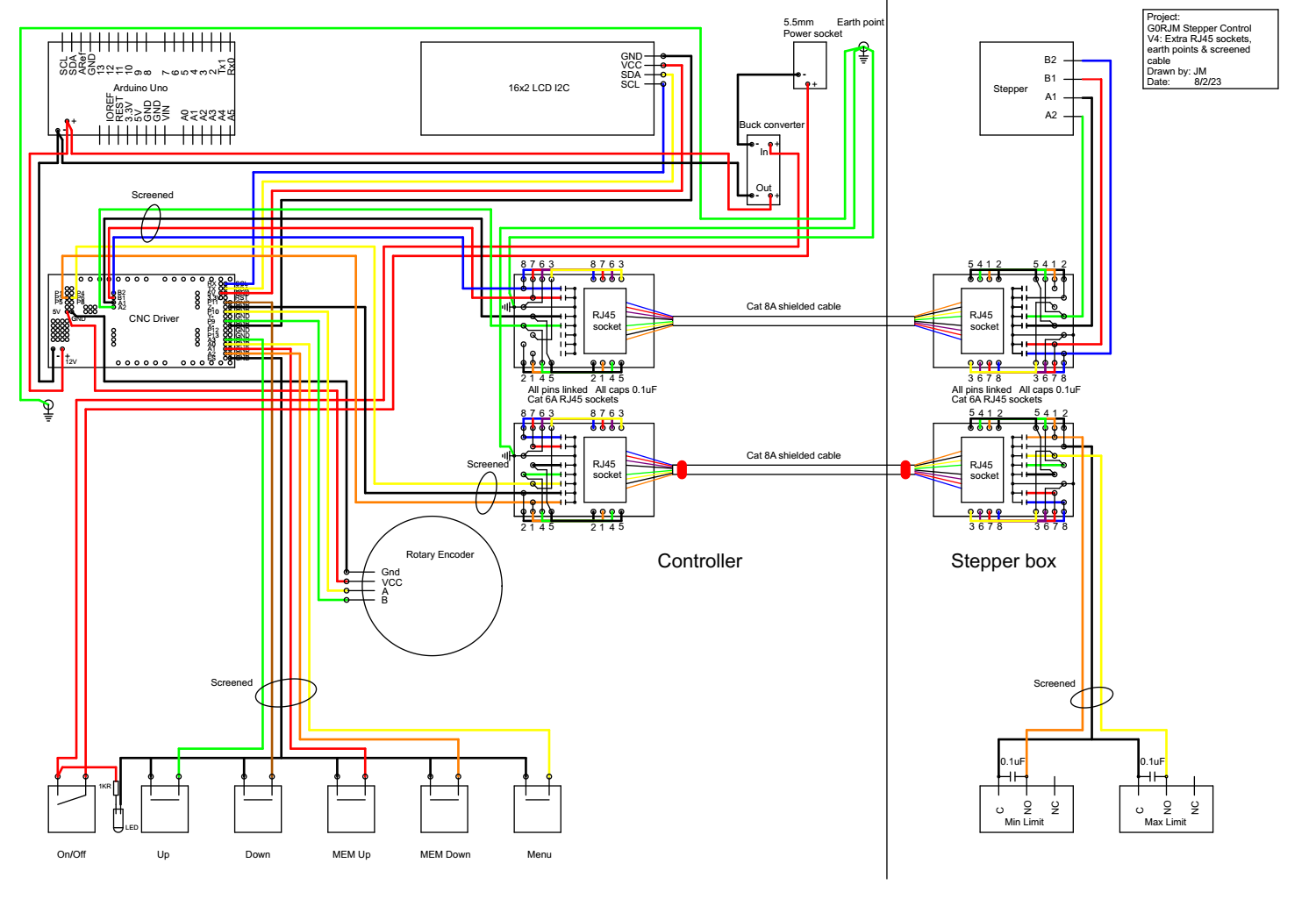
I am building an Arduino-based remote controller for a stepper motor-driven variable capacitor for a magnetic loop antenna to be used with an amateur radio transmitter, which will create a fairly high amount of local RFI. To prevent the RFI from getting back up the interconnecting cables, I have installed 50V 100nF ceramic decoupling capacitors on both RJ45 sockets between each core of the Cat8 shielded cable and true earth. The micro step plugs have been fitted to give 1/16th step function. The problem I am getting is that the stepper motor just makes a high pitched noise and does not move. If I connect the stepper motor directly to the A4988 driver, the stepper works fine in both directions. The Nema 17 stepper is rated at 12volts and the feed to the A4988 driver is 11volts.
The conclusion I have drawn so far, is that the decoupling capacitors maybe somehow causing the operational problem. Should I reduce the value of the decoupling capacitors or remove them?
What else clould be causing the system to not work when using the 15 metre long Cat8 shielded cable? I have checked that both of the RJ45 plugs on the Cat8 cable are wired in the same format. Your thoughts would be most helpful.
You could try reducing the value of the decoupling capacitors to see if that solves the problem. The 15 meter long Cat8 shielded cable’s resistance could be affecting the voltage level, causing the stepper motor to not work properly. You might consider using a shorter cable or a higher-gauge cable to reduce the resistance.
Hi, Johnem.
It is not clear to me from your diagram where you installed the capacitors. Could you draw a simple schematic that shows where they are in relation to the drivers and motors? In general, the stepper motors should be directly connected to the drivers with nothing between them and nothing else connected to the driver’s motor outputs.
-Claire
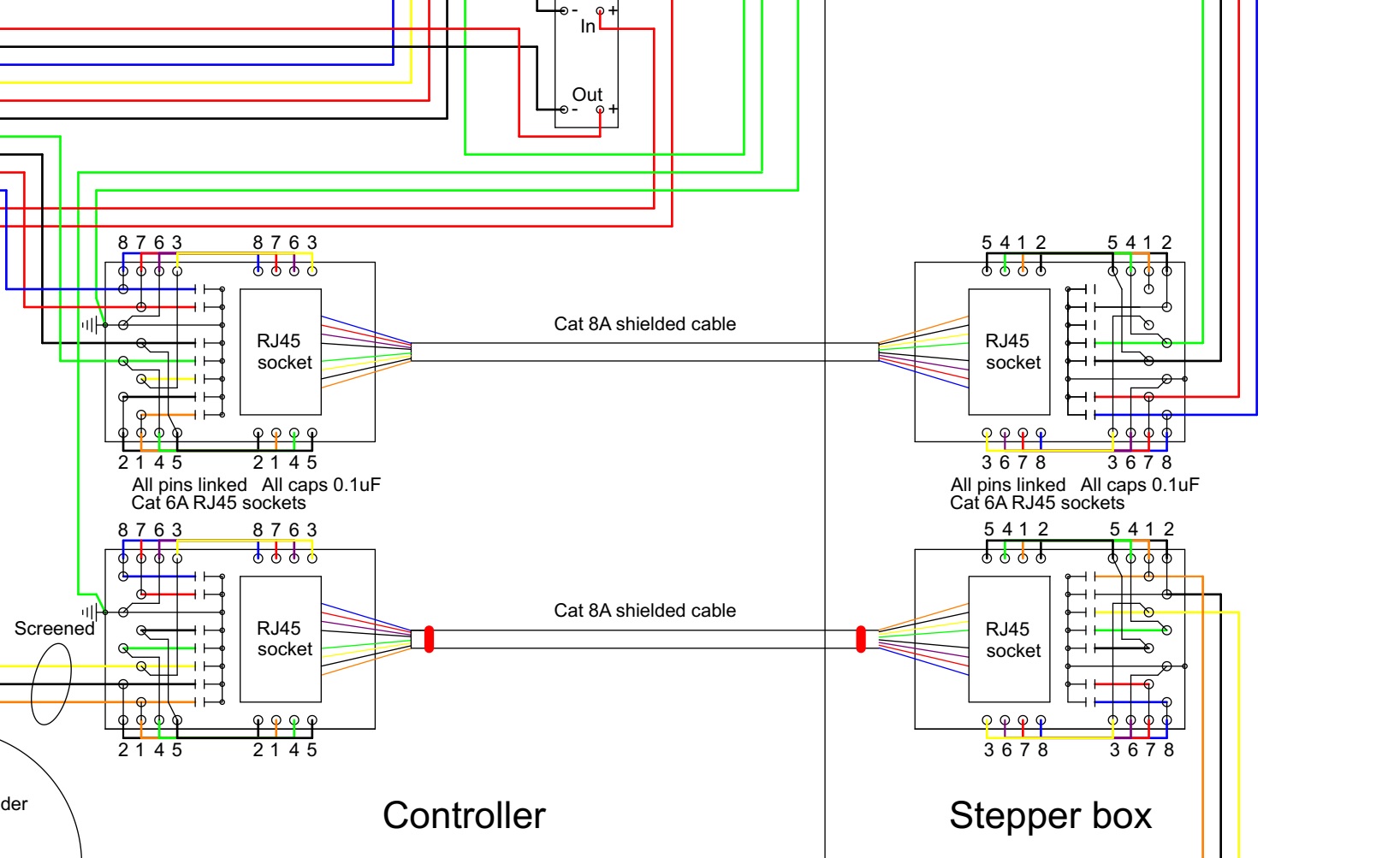
Evening Claire, please see the enlarged section of my wiring diagram below.
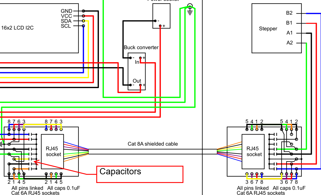
The 100nF capacitors are shown linked between each pin of the RJ45 socket down to real earth. As mentioned, these were included to prevent RFI getting back to the stepper driver, but can be taken provided that you do not think the A4988 driver will not be effected by the potential presence of RFI.
I have tried running this with a 1 metre Cat 6 cable and get the same results, so I do not think that on this occassion the length of the cable is the full problem. It may be contributing, but I need to do some more investigating. Thanks you for your help.
Could you post more information about the board that your RJ45 connectors are on, like a link to their documentation or a schematic of them? Is it possible for you to remove the capacitors temporarily for testing but keep the rest of your setup the same? Could you post pictures of your system that show all connections?
-Claire
Afternoon Claire,
Thank you for your e-mail.
I will sort out the information that you have requested and get what I have across to you as soon as I can.
Thank you for your help so far.
73’s
John Marchant
G0RJM
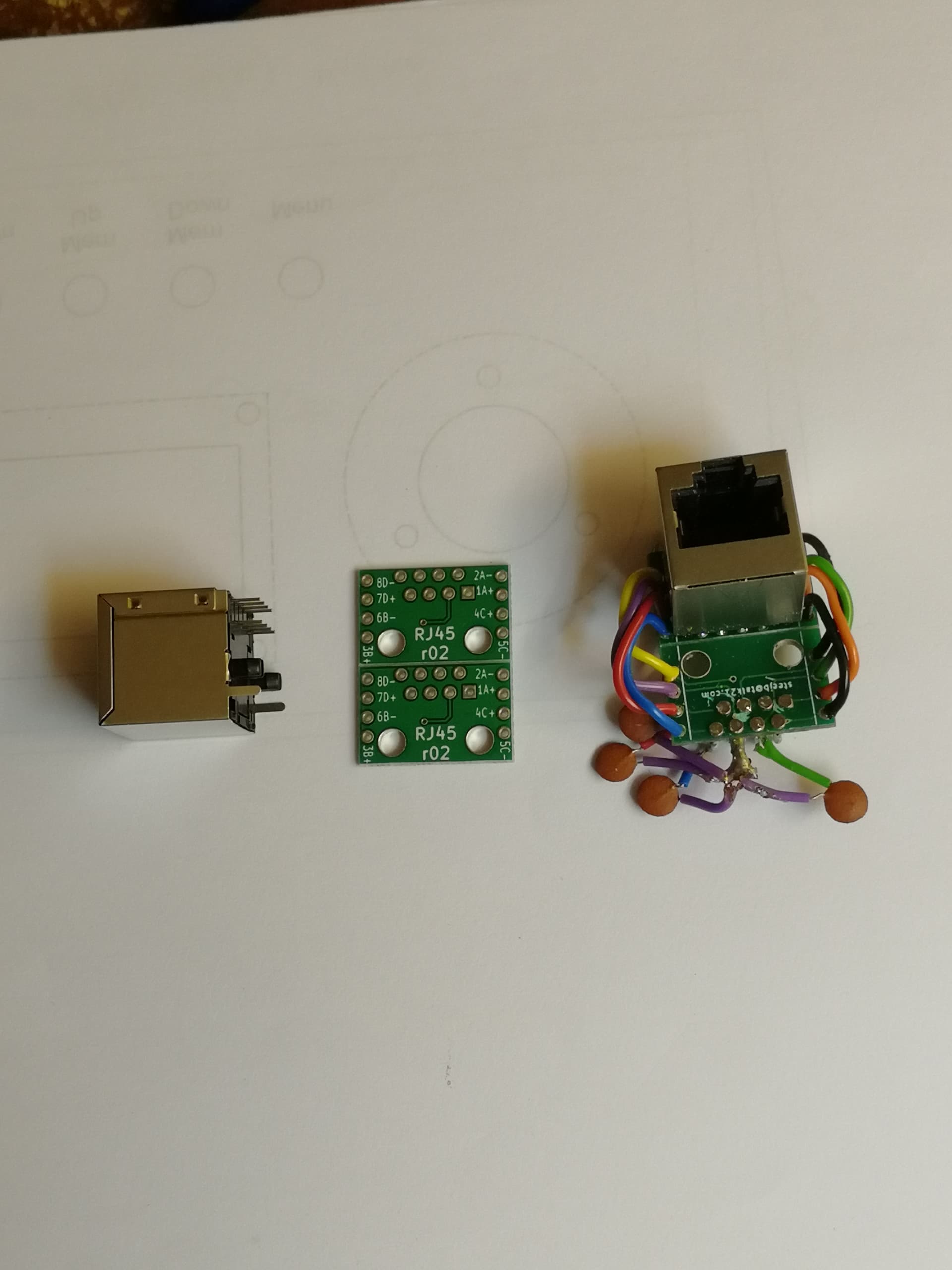
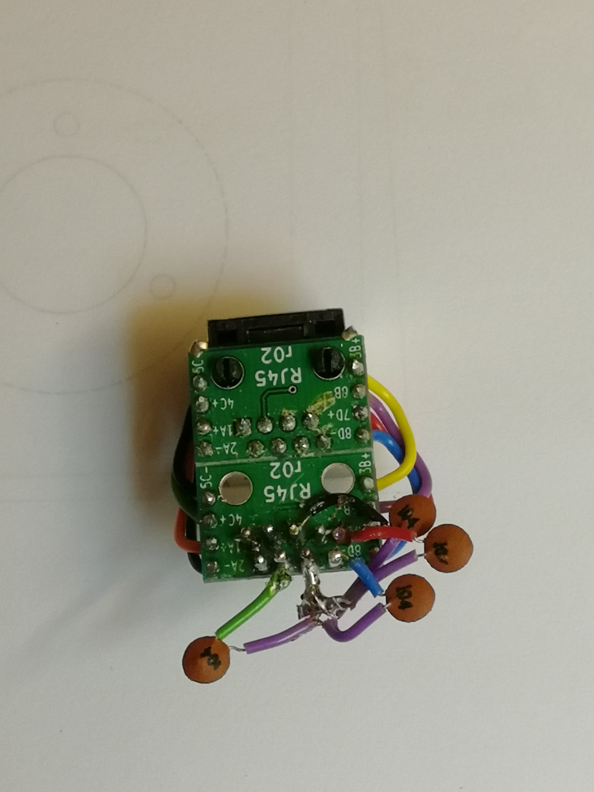
Afternoon Claire, sorry for the delay in replying.
Here are some photos of the RJ45 header that I am using along with the screened RJ45 socket and one of the headers complete with decoupling capacitors.
This is the enlarged wiring diagram showing the connections to the stepper motor and driver.
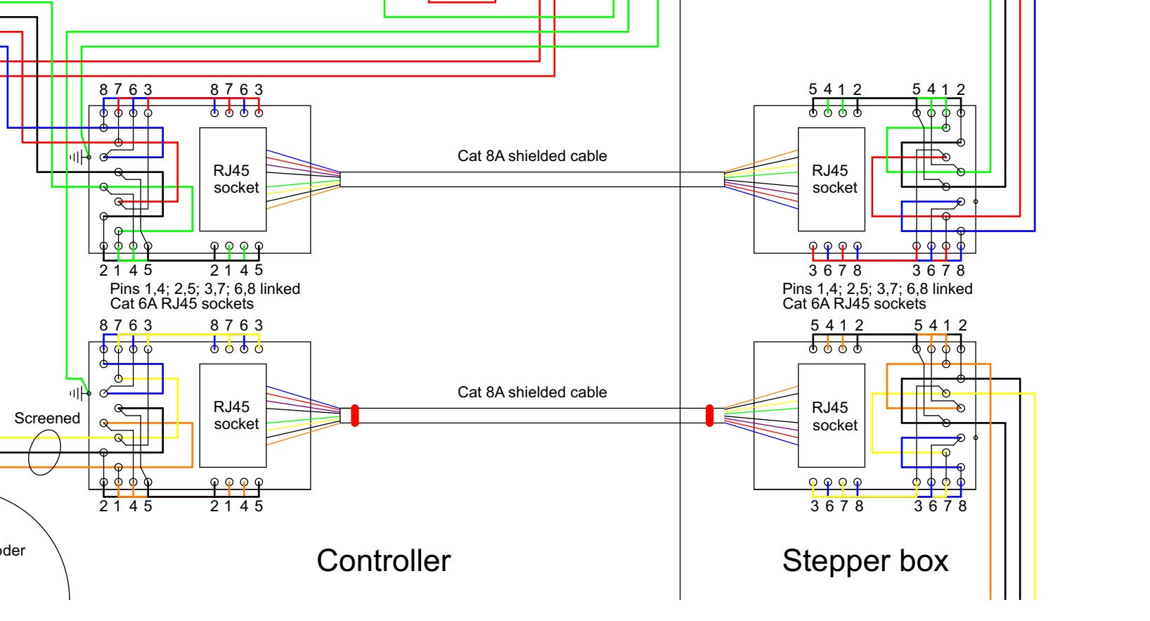
The connection from the internal RJ45 to the driver are now in a screened four core cable and the internal end switch wiring is also now in a screened cable.
I am in the process of rewiring the RJ45 sockets without the deoupling capacitors and I am doubling up the connections so that each output from the driver is carried over two cores, connected in parallel to reduce the line resistance.
I am running two twisted pairs for the A+ and A- stepper connections and two twisted pairs for the B+ and B- stepper connections.
The wiring from the external RJ45 is now run as twisted pairs in an overall screened cable.
The external end switch wiring has now been upgraded to twisted pairs in an overall screened cable.
Some of the wiring within the Arduino enclosure has now been upgraded to screened cable to try to minimise any potential interference caused by the stepper motor form affecting the low voltage data signalling.
This is the enlarged revised wiring diagram.
Please let me know if there is anything else that you would recommend be changed.
It isn’t clear whether you have done more testing after making those changes to your setup, but if you are still having issues, I recommend starting with the case that worked, the motors directly connected to the drivers, and then adding one thing at a time until it stops working. For example, after confirming that a direct connection still works, you could start by connecting a motor and driver through a short length of unterminated network cable (to keep the RJ45 connectors out of the picture). Then, if that works, you could try adding a connector on one end to see what impact it has.
-Claire
Evening Claire,
I have followed your advice and removed the decoupling capacitors from the two RJ45 sockets at either end of the interconnecting Cat 8 shielded cable. The remote control of the stepper motor now fine works without any interuption or strange noises. This setup has now been tested with the 15 metres Cat 8 cable fully unwound and with it in a loose coil with no noticeable adverse operation. I have also been able to reduce the driver external supply voltage to 9volts and the stepper runs fine.
Thank you for your help on this project.
Regards John.