D24V6F5 problems starting up

Some background:
I have a robot that runs on 16V (4S LiPo.) As a back-up, I also need to run the robot on 3S (12V.)
The controller for ther robot is an openCM 9.04 board.
This board has an input 5V regulator rated for 20V input, and a rated drop-out of 0.8 - 1.0V.
The board also has a large-ish input electrolytic capacitor (I think 100 uF?)
The board power draw is from a dozen to 50 mA. (Its main power sink is a STM32 ARM MCU and a 74125 style TTL bus driver.)
However, when I feed 16V straight into the board, the regulator gets hotter than I like, Dropping 50 mA from 16V to 5V is about 0.6W, so I can see why!
The board is rated 5V to 16V, but as I said, the input regulator is 0.8V drop-out and up to 20V input.

Solution: Get a D24V5F6 to put between the 16V battery and the power input on the OpenCM.
Given that the drop-out is rated between 0.8V and 1.0V, this should work fine, and leave the regulator as cool as possible.

Unfortunately, when I start up (a MOSFET based power switch,) what happens is that the board power LED just glimmers weakly, and the board doesn’t get to the start-up code that blinks anoter LED. It seems to be in brown-out.
Measuring the output from the D24V5F6 at this point shows about 3V output! It never goes out of this mode.
When the OpenCM is not plugged in, the D24V5F6 starts up fine, and outputs 6.06V, which is perfect.
When the OpenCM is plugged in, and I don’t use the D24V5F6 , it runs fine. (But the linear regulator gets hot.)

Knowing how finicky switching controllers can be (they’re really just oscillators with a negative source impedance, and might easily go into all kinds of weird feedback loops,) I wonder if there’s something in this setup that causes the D24V5F6 to latch in “bad” mode on start-up. Something like over-current beacuse of inrush, or some unfortunate interaction with the particular rise time and power spike when the MCU first powers out of brown-out, perhaps?
Does this ring any kind of bell? Is there some kind of easy fix you know about?

I have other options, such as a 7.5V buck converter, or a linear regulator instead of the switcher. But the 6V looks so nice, and leaves everything so cool, in theory, so I’d love to get it to work!

Hi.

I tested one of those regulators here and noticed that it has a hard time starting into loads near its maximum output current (around 600mA) and large capacitive loads. Does it work with your OpenCM board if you turn on the regulator first and then connect the board? Is it practical to put your power switch between the regulator and OpenCM board? If you have a scope it might be interesting to look at what happens with the output voltage (and current if you have a current probe) when starting up.

-Claire

Thank you for the answer!

Testing with a linear regulator, the board actually operates down to 4.0V input, although the 5V dependent parts (mainly a TTL driver) drops the output voltage. The CPU itself only needs 3.3V (which is fed by a second regulator on the controller.)

The steady state power draw is 130 mA, which I think is a bit high for a microcontroller, but whatever. It’s not 600 mA!

My guess is that the start-up of the regulator somehow fights with a boot-up / brown-out detector on the controller, such that it never actually gets going. Measuring the output of the D24V6F5 at this point shows about 3.95V.

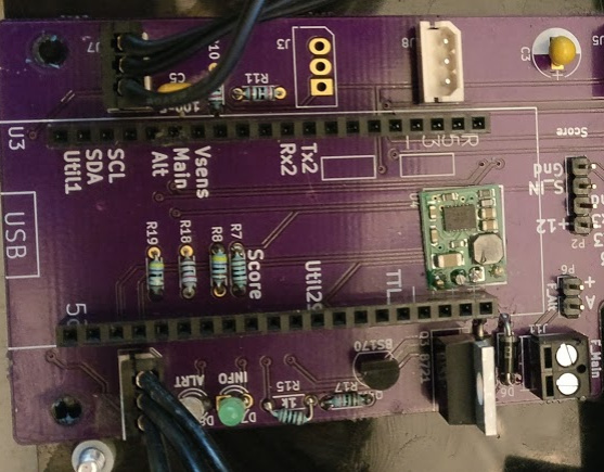
While I do have a 'scope, I didn’t have time to hook it up, because I had to solder the D24V6F5 right onto the circuit board (hole to hole) without pins/sockets, because I had very little space left on the board when I added this at the last minute. It goes underneath the socketed MCU board! The design of the D24V6F5 actually lends itself to this “ghetto surface mount” option because the back is entirely flat – no through-hole components, single-sided board.

This is the regulator soldered to the board, underneath the controller socket:

The power/ground pins on the MCU are the four pins in the bottom right of the socket, right next to the regulator.

Unfortunately, this also means that putting a second power switch between the regulator and the MCU isn’t really going to happen. Not only would I have to re-make the PCB, but I’d also have to flip this switch while holding down the regular pushbutton power-on, because the MCU powering up and driving an output pin is what pulls the P-FET on switch gate down. (This way, I can power off when the battery voltage gets low, to avoid killing the LiPo that drives the whole thing.)

Long story short: I’m going with a linear regulator for this application for now. I’ll still be using another Pololu regulator (5V) for driving the wireless camera that’s also on this robot, so it’s not an entire loss for you guys :slight_smile:

Looking back at your first post I noticed that throughout it you refer to using the D24V5F6 regulator, but the title is about the D24V6F5 regulator (which we also have,but is different). From the picture it looks like you did mean the D24V5F6 regulator, which is the one I tested.

In your last post though, you refer again to the D24V6F5 regulator. I tested one of the D24V6F5 regulators today and did not have any trouble getting it to start with a heavy load or capacitive load. It is the same size and pinout as the D24V5F6 regulator, so it might work for you.

-Claire

Ha! I got it wrong in the text, and then copy-pasted it. The one you think I have, and which you tested, is in fact the one that I intended. Sorry to be so confusing.

Also, have you considered a less-confusing way of naming these? :slight_smile:

I totally understand the mix up. I’m not sure how serious you are about the name, but if you are, do you have some suggestions?

-Claire

Ha! Your scheme seems to kind-of sort-of map to the input and output voltage and current limits. However, when you have old and new generations with similar major specifications, telling them apart becomes harder. If it were me, I’d name them something like:

Buck-G3-24V-06V-05A[-Adj]

The dashes help separation. (underscores would work, too, as would spaces even)
The first is the major class – Buck, Boost, SEPIC, BuckBoost, …
The second is generation – G3 for the third generation of designs for the major class of converters.
The third is the maximum recommended input voltage.
The fourth is the output voltage, or for adjustable converters, the maximum output voltage.
The fifth is the current limit to the nearest 100 mA.
The final is only there if it’s an adjustable converter.

That’s my free advice, and worth every penny you paid for it!