I am attempting to supply 6V to the motor voltage input of your TB6612FNG (item #713) to drive one or two Micrometal Gear Motors (item #2218) with the D24V6AHV adjustable stepdown converter.
I am currently driving the input voltage to the converter with a lab bench supply set at 12V. With one motor connected to the driver with no load on the motor, the voltage from the regulator “immediately” drops from its 6V setting to approximately 2.4 volts during the PWM pulse and then returns to 6V. The current draw from the motor when I apply the maximum load that will be applied when the motor is connected directly to the lab supply at 6V is about 220mA. I had assumed that I could get about 550mA of output current at 6V with a 12V input by doubling the output current shown on the graph of the converter page for the 300mA version. There is no graph shown specifically for the 600mA version so I doubled the 300mA values.
With the regulator set for an 8V output, the output voltage also drops to the same 2.4V level during the PWM pulse.
I have not added any heat sinks so far but the regulator is not hot to the touch.
My guess is that the converter is going into output current limiting (shutdown) due to the current spike when the motor starts (I guess stall current is drawn on startup?) on each PWM pulse but it does not seem to recover during the pulse even though the current requirement is very small with no load (< 50mA). If this is the case, I am hoping that adding more capacitance on the output alone will help but maybe I need to implement something more complicated to limit the motor start-up current (series inductor…). I don’t have a scope trace picture handy but could post one tonight if that would be helpful.
So my questions are:
Do you have an alternate explanation of what is happening?
Does the drop to 2.4V indicate anything in particular?
What does the output current have to drop to for the over current circuit to reset?
Thanks
With a 12V input and 6V output, I expect the D24V6AHV to be able to output up to 600mA. Although there is no available output current graph for the 600mA versions of this regulator, you can get an idea of the amount of current they can handle by looking at their efficiency graphs.
I am not sure exactly what is going on, but if your regulator is getting very hot and the output voltage is dropping, it seems like the current draw of the motor is probably too high for the regulator. You mentioned that your motor is only drawing about 220mA. How did you measure that? You also mentioned that the regulator’s output voltage only drops “during the PWM pulse”. Do you mean that the output voltage drops every time the PWM pin on the TB6612FNG is driven high and then returns to 6V every time the PWM pin is driven low? If so, how are you measuring those voltages? What frequency is your PWM signal?
That regulator has a current limit of a little over an amp, so if your motor is drawing its full stall current when it turns on, it is possible that the over current protection of the regulator is getting triggered. If the issue is that the inrush (start up) current of the motor is too much for the regulator, you could try gradually ramping up the speed of the motor to minimize the current spike.
Thanks for the response. I copied some scope pics on to a flash drive but am having problems reading it so I will try to convey what I found out in millipictures (words).
First I checked to make sure the converter was working properly. With a 12V input not going into current limiting, I loaded the converter with 25 ohms and set the output voltage to 6V.
With a load of 10 ohms the output was 5.8 volts (580mA) and with a load of 5 ohms the voltage was 3.3V (660mA) so it all looks good for the converter. I did this with a big rheostat I keep around for these kinds of measurements.
Then I hooked up the motor driver and of course because I was going to include the scope picture I didn’t write down the values exactly but basically because the driver pulls almost no current when there is no PWM pulse on the motor controller the output voltage was about 6.6V (6 volts set with 25 ohm load). And the output dropped to about 4.8V (not 2.4 as I reported earlier although 2.4 could have been with both motors connected).
Long story short putting a small load on the converter all the time is helpful in terms of reducing the differential between the unloaded and loaded output voltage but what really helped was the addition of a 68uF 35V electrolytic cap. I think with the cap the voltage only dropped to 5.5V during the pulse.
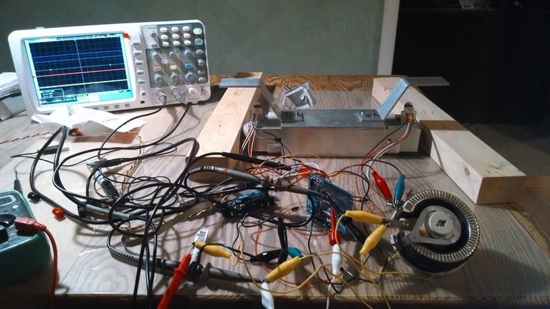
My application, BTW is not normal for motor control. I am working on a system to move a camera dolly that rides on rails back and forth. It is basically a spring loaded tube that hangs below the dolly and presses two drive wheels against the inside of the rails. In the pic the two pieces of wood are being used as test rails. Control of each motor is independent so it can navigate curves. Anyway, it needs to move the dolly from 1 in/minute to about 10 inches/second. So that is a wide range. To get this range, the processor decides on one of two motor control modes which I call variable period or variable pulse width (normal PWM). When the motors need to turn really slow, the PWM period might be something like 1 second and the pulse width might be 20ms. So the DC brushed motors are being jogged and kind of act like a stepper but with a lot more torque for the size. In this mode, for the “master” motor, the pulse width is always the same and the period (always subsonic frequency) is varied to close the loop between the set point and the encoder. The other motor runs from the same hardware counter on the other compare output and its pulse width is varied so that the motors run at the same speed. So, in this mode, the motor is starting and stopping with each pulse and that was what was causing problems with the converter. As soon as the dolly is commanded to move fast enough so that the motors never stop turning, control switches over to a hypersonic PWM frequency and the pulse width for each of the motors is varied in the control loop like a normal PWM control application.
I am glad to hear that it sounds like you got the regulator working in your setup with the additional load and capacitor. Your dolly application sounds interesting; I would love to hear more about it, or see more pictures or video when it is all set up.