I’d like to design a board with a microcontroller that can be powered both from a bus with the stepdown regulator D24V5F3 (or alternatively D24V5F5), and from the programming connector directly with 3.3 or 5 V. The microcontroller supports both voltages (ATtiny1614).
Now is there a problem when the external bus is disconnected and the voltage regulator remains unpowered at VIN, if a positive voltage of 3.3 or 5 V appears at VOUT?
If this is okay, can the backwards voltage be 5 V for the 3.3 V regulator, or 3.3 V for the 5 V regulator? Or does it have to match the regulator output (how closely)?
If it’s not okay, what solutions would you suggest? I thought about a Schottky diode that only allows voltage from the programming connector to the microcontroller but not to the VCC of the remaining circuit (including the Pololu regulator and an RS-485 chip). That diode will have a voltage drop that causes the microcontroller and the RS-485 chip to operate at different VCC. The MCU only accepts 0.5 V higher IO voltage, above that a resistor is required.
Another idea with probably less voltage drop might be a P-MOSFET reverse polarity switch, but I haven’t found out yet how that would work.
It is not good to apply voltages to the output of a regulator, even when it is not on, and it could damage your regulator, so it would be good to design your circuit to avoid that type of condition. There are plenty of ways you can do that; using a diode like you described is probably the simplest, and a reverse voltage circuit with a P-channel MOSFET could work too.
This YouTube video has some information on reverse voltage circuits that you might be interested in.
Thank you, that video was indeed helpful. Now I can design my reverse polarity protection. I could also verify its function in an LTspice simulation, as far as I could select similar elements.
But I can’t get the backfeeding protection to work. What I’d like to do is the following.
There is a system supply (V1) that is provided by the Pololu LDO with an output voltage of 5 V. It supplies the entire system, including the MCU.
There is also an additional supply (V2) that comes with the programming interface. This is the Atmel UPDI interface which I connect to a USB/Serial interface which also provides 5 V. This voltage must only supply the MCU, not the rest of the system.
The system LDO (Pololu) is always connected because it will be soldered onto the board. It must be protected from backfeeding automatically.
The UPDI supply is only connected for programming the MCU and will be disconnected when the system supply is on. So it does not need to be protected from backfeeding.
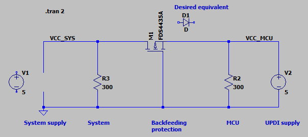
How would I have to connect the P-MOSFET to achieve this? When I do it the same way, it isn’t effective. Here’s what I did. The current state shows the system supply off (I have taken it out of the circuit but in reality it will be there but unpowered) and the programming supply active.
The expected result is this: VCC_MCU is 5 V and VCC_SYS is 0 V, i.e. the MOSFET is “off”. The additional diode at the top describes this situation, but its forward voltage drop will be too high so I can’t use it.
The actual result is this: Both VCC_MCU and VCC_SYS are around 5 V, i.e. the MOSFET is “on”. The programming supply also feeds the rest of the system.
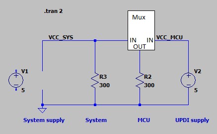
A MOSFET by itself will not work for your situation where both sides have power sources (the reverse voltage circuit is meant only to protect against a single source going negative). You could add a pair of transistors to make the same ideal diode circuit used on the Raspberry Pi. How it works is explained in this stack exchange thread. Another approach would be to use a power multiplexer like our TPS2113A Power Multiplexer Carrier between your programmer’s 5V output and your microcontroller as shown in this modified version of your diagram.