I’m trying to use the D24V150F5 step-down regulator to power a 5V LED strip and a 5V Raspberry Pi. However, my regulator seems to be continuously going into the “Error State” with the EN pin on low voltage.
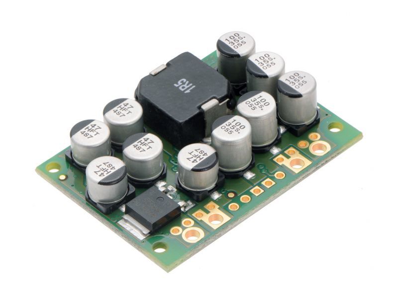
Here is a picture of my setup. I have verified all of the terminals are correctly soldered.
The behavior is such: Sometimes, when first plugging in my lipo for the evening, it will work successfully and I am able to power my LED Strip/etc. However, when removing the lipo and re-inserting, it will no longer work. At this point, it will not work from then-on.
I am powering with a 3S lipo @ around 12V. The terminals at the VIN on the regulator properly read my battery voltage. However, no output voltage can be read. When the regulator stops functioning, the EN will read low voltage (around 0.3v or so). When functioning, the output terminals will properly read 5V.
When the regulator stops functioning, I am unable to get it out of this “Error State”. EN will continue to read low voltage and there’s seemingly nothing I can do to bring it back up. I am curious as to why it will work initially, and then cease to function. I believe it’s because I enter this Error state, where the EN reads low. It then will take some time for the EN to bleed out the voltage, at which point it will operate – one time only – again?
Is there any reason why my lipo source will cause this behavior on this regulator? It’s 12V is well within the specs of the regulator.
As of this morning, the EN reads 0 voltage, no output is still produced when lipo is connected. No EN voltage is present when battery is connected. Not sure if this means the reg is dead?
It looks like the solder on the GND of the input screw terminal is balled on the pin and not wetting the pad. A bad solder connection could cause a problem like you described. This board uses thick copper and has a large surface area, so it might take a little more heat than usual to get a good connection. You can find examples of good an bad soldered joints and tips for making good joints and fixing bad ones in the Adafruit Guide to Excellent Soldering. Can you try retouching connections?
I updated my solder joint just to be sure. It now completely covers the pad on the board. I re-tested with the battery and it still produces no output voltage. My multimeter, when placed on the board’s VIN/GND pins, confirms the input voltage is properly coming through to the board. The black thing on the board (sorry, I’m not technical) also warms up. However, EN reads 0.0v , as does the GD. No output is produced.
Were your latest tests without a load? If you have a good input voltage to the regulator, no output voltage and nothing else connected, then the regulator is likely damaged. Which side of the board is the black thing you referred to located? How warm does it get? Has the regulator always had this issue? If you post more information about how you were using the regulator and your load (do you have any more specifications for the LEDs?), we might be able to help you determine how the damage happened.
The part that says 1R5 on top. This part warms up when I plug in my lipo battery source, which seems expected, right? Is this a good sign that the regulator has some function still? It gets warm - not too hot to touch. I’m only using a 12V source so the reg can handle much more.
The regulator has always had this issue. I’m powering a Raspberry Pi and a 0.5 meter DotStar strip which has 72 pixels at 60mA per pixel which according to spec should pull a little over 4A max.
The inductor getting warm does not tell us much. If you happen to have access to a thermal imager and can pinpoint which other components are heating up, it might be helpful. In the meantime, if you email us at support@pololu.com with your order information and a reference to this thread, we can see what we can do to help you out.
Is the Dotstar strip you are powering purchased from Adafruit? I’m asking because strips of Dotstars and also their Neopixels have very strict power requirements. I am not sure it is a good idea to try powering 72 pixels plus a raspberry pi all from a single 12v lipo battery. That is a heck of a drain on the battery itself and it could be pretty hard on the regulator. 72 pixels is just a lot to power with the battery.
Adafruit has a very good tutorial on powering their Neopixels which should also apply to the Dotstars. I have a couple of the Neopixel strips and I use a 5v 10A power brick sold by Adafruit to power the strips with. I also have some Dotstar LEDs which I’ve soldered to individual PCBs and I power these (only 4 of them for now) with with a 5v 1A wall supply.
Bob: The DotStar strip is Adafruit, yes. According to their site, 72 pixels should be about 4.4A max. The Lipo Battery is a 3S 1300mah battery, rated for 45C continuous current. This battery easily pulls up to 25A while flying a quadcopter, and can handle any load the DotStars will end up pulling from it.
Brandon: OK, I will write up an E-mail. I don’t have any kind of thermal imager, so I can’t provide any of that information. Thanks.
I guess I would be really cautious here about using 12v lipo input and reducing the voltages for this application – of powering DotStars specifically. I know it is possible, of course. But the Adafruit Neopixel Uberguide, available here, which also applies to DotStar strips, sticks to 5v or 3.7v power sources as input for the pixels. I highly recommend you take a look at the section on Best Practices on page 34 and “Powering NeoPixels” on Page 35.
Adafruit hosts great user forums too, and you might want to search their forums for issues similar to yours (and there are lots of others who have posted issues on powering the pixels), or post a question there about how you are doing this. As with most technical forums, you will be asked to post really clear photos of your circuit. So you might want to do that too.
Bob, I’m not sure I understand the risk with using a voltage regulator to go from 12V to 5V. I know that it’s not listed on the Adafruit site, but what is the risk in doing this?
A voltage step-down circuit is not in the Adafruit “Uberguide” for Neopixels. There must be a reason for that. Perhaps you can post on their forums as I mentioned above and inquire. That is all I’m saying.
I would not expect any problems with powering the DotStars (or similar LED strips) from a regulator, as long as the regulator can handle the current demands of the system.