Hi,
I have a couple of questions regarding a project I’m putting together. I’m a relative beginner at this so please bear with me…
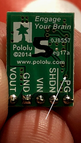
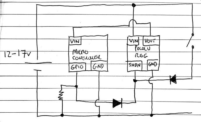
I have a D24V10F5 which I’d like to control using a switch and an Arduino board. I’ve enclosed a schematic of my proposed circuit and a pic of the regulator. I would like to be able to turn on the regulator / microcontroller using a switch and then have the microcontroller turn itself off in software. I’m aware of the Pololu pushbutton switches but I’m really pushed for size in this project.
My plan is to first of all break the trace annotated on the pic in order to cut the connection on the Pololu regulator between SHDN and VIN.
As illustrated on the schematic, closing the switch will turn on the regulator and power up the microcontroller. The microcontroller GPIO pin will immediately go high (3v) so that when the switch is released, the regulator will latch on.
When the board needs to turn itself off, the GPIO pin is sent “low”, turning the regulator off.
My questions…
First of all does this sound correct / feasible?
Will the SHDN pin be pulled “low” correctly in the above instance through the diode? I’ve added a pulldown resistor to the GPIO output, but I’m not convinced it’s needed.
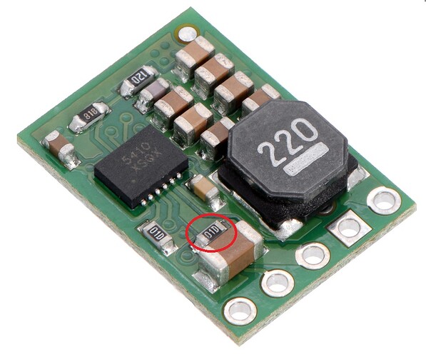
Secondly - have I got the correct trace to cut on the Pololu regulator? I’ve considered attempting to remove the resistor but it looks too small for my big clumsy fingers.
Many thanks in advance!


