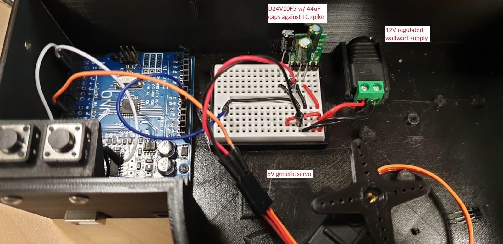
For my project I’m trying to power a generic 4.8-6V RC servo (link here) through a D24V10F5 5V buck regulator, itself powered by a 12V wallwart.
I’ve ensured the following:
- The servo and Arduino Uno i’m using to control it share common ground.
- A 44uF cap is between Vin and GND on the 5V reg to prevent LC spikes
- A 100uF cap is between Vout and GND on the reg to stabilize output voltage
- The reg pushes a max of 1A while the servo was tested to draw only 300mA peak at 5V.
- The 12V wallwart outputs max 1.2A.
I tried running a simple turn and return code as below:
#include <Servo.h>

Servo thisServo;

void setup() {
  thisServo.attach(10);}

void loop() {
  thisServo.writeMicroseconds(900);
  delay(3000);
  thisServo.writeMicroseconds(1800);
  delay(3000);
}
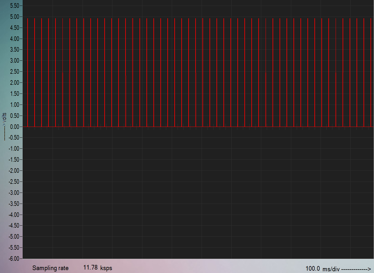
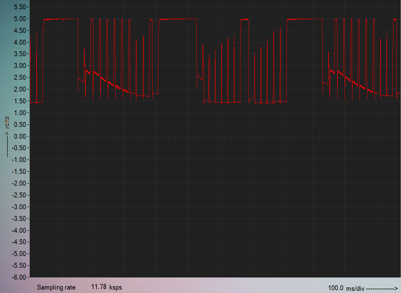
this resulted in extremely erratic motion. From what I can observe the servo will hit the 900us position and immediately and rapidly oscillate between 900us and 600us for 3 sec, then move to 1800us and oscillate between 1800us and 600us for 3 sec, and continues looping like that. 600us is roughly the position of the clockwise stop for this servo, and telling the servo to hold any value seems to make it oscillate between that and 600us.
I tried two suboptimal workarounds that appeared to work:
- Plugging the servo directly to a 5V wallwart works perfectly.
- Curiously, extending the positive lead of the servo via a 60cm crocodile wire seems to work as well; the longer the wire, the less oscillations are observed. I discovered this when testing the current draw with a multimeter.
I feel like i’m missing something frustratingly obvious here, but i don’t know what, and unfortunately I don’t have an oscilloscope to test this for myself. Does the D24V10F5 generate a lot of EMI which interferes with the servo PWM?