I’m using the D15V35F5S3 Step-Down Voltage Regulator with a 2S1P / 7.4v / 2Cell Lipo Battery to control two 30mm 5V fans that draw .46 AMPS, an LED chaser that draws 1.3 AMPS, two 24 pixel NeoPixel rings and two Arduinos.
My setup was working fine for about 5 mins, until I stopped getting voltage output from the regulator. The battery was already connected to the regulator when the failure happened so I don’t think it was caused by jiggling the connector (D15V35F5S3 unreliable).
I double checked continuity of inputs and outputs with my multimeter. I read 8.04 V from my battery. I read 8.04 V from the input posts on the regulator and 0V from the posts output posts on the regulator.
The board itself gets warm with the battery plugged in.
What can I do to troubleshoot this board?
If it has latched off, how do I reset it?
Hello.
I am sorry you are having problems with your regulator. It sounds like your regulator is damaged. You might have exceeded the current capabilities of the regulator with those components all powered from it. The 24-LED NeoPixel rings can draw 1.2A each, so with just the 2 LED rings and the LED chaser, you could have exceeded the 3.5A rating of the regulator.
You might try testing the regulator without a load connected to it. If the board is latched off, you can power cycle the board to turn it back on. Alternatively, you can drive the EN pin low to reset the latch.
- Jeremy
Hi Jeremy,
Thanks for your response. I should have clarified in my original post. My regulator is the version that is rated for 7A continuous (pololu.com/product/2111) . And in my actual test where the board shutdown, only one of the 24-LED NeoPixel rings was attached to the circuit.
I have removed the battery and re attached it to power cycle the board and removed the load, but I’m still not getting any voltage output.
Do you have any other suggestions?
The 7A version can source enough current for all your devices, so I am not sure what might caused it to stop working. Could you tell me more about your setup? What is the capacity and C rating of your 2S LiPo battery? How were all the devices connected? Could you post pictures of your setup?
- Jeremy
Hi Jeremy,
Thanks for your help so far.
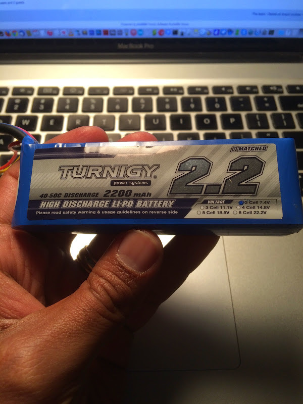
This is my battery:
hobbyking.com/hobbyking/stor … _Pack.html
The C rating should be:
2.2X 40 = 88 amps continuous discharge.
I’ll try to describe my setup the best I can.
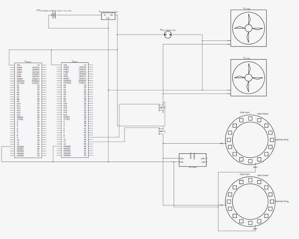
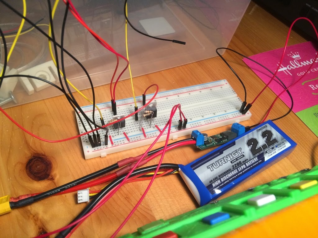
The battery is attached to a XT60 connector which is attached to the step down input. Two jumper wires are connected to the step down output which are connected to a solderless bread board. Power to the fans, LED chaser and NeoPixel ring are controlled via P channel MOSFETS (1 MOSFET for 2 30mm fans, 1 MOSFET for LED chaser and NeoPixel ring ). The two Arduinos are powered via the 5V rail on the breadboard to their VIN pins.
Here’s a simplified schematic:
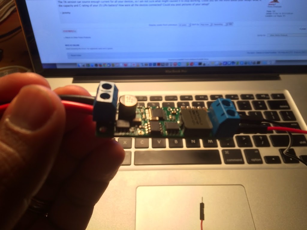
And here’s some pics of my setup which I’ve tried to simplify as much as possible by showing only the power connections:
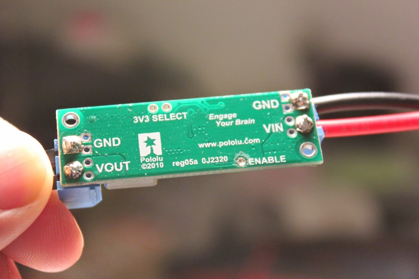
Thank you for posting those pictures. The connections between the terminal blocks and the board look like they might not be making good connections. Could you try retouching the pins with a soldering iron to make sure the pins make good connections with the board? You might find this soldering tutorial helpful.
- Jeremy
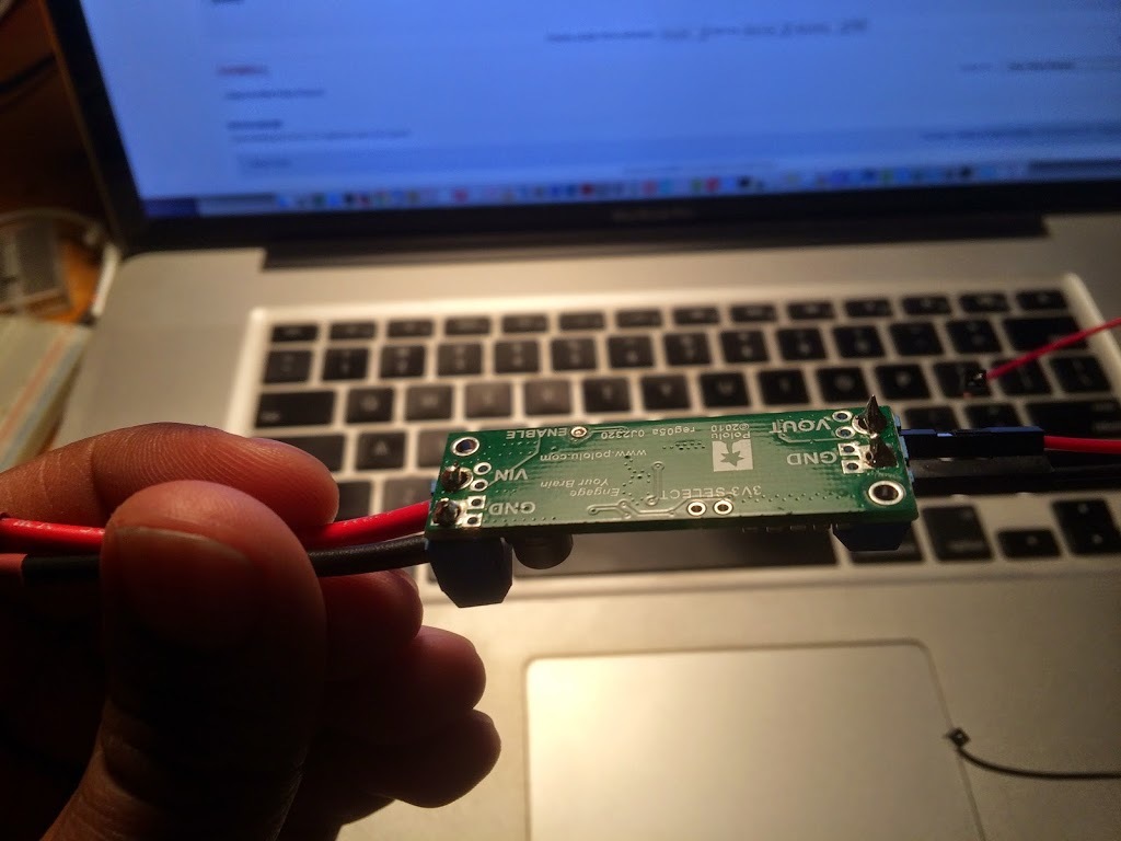
I did notice that the pins on the terminal blocks are much smaller than the through holes provided on the pcb.
I resoldered the connections so there are no gaps in the through holes:
I tested for continuity with a voltage meter between all for leads and all the pads on the pcb. They all tested fine before and after resoldering.
There is still no voltage output. Is there any thing else I can do at this point?
Were you measuring the voltage at the terminal blocks? If so, it does sound like your regulator is damaged. If you contact us directly at support@pololu.com with your order information and reference this forum post, we might be able to help you with a discount on a replacement.
By the way, I noticed that you are using a solderless breadboard in your setup. You might refer to the breadboard’s specifications to see how much current it can handle since they are typically only good for up to an amp.
- Jeremy
I was measuring voltage at the terminal blocks. What happens if I bought the regulator from a Pololu vender (robotshop.com/ca/) and not from Pololu.com directly?
I just noticed this comment on their product page:
“From my experience, the enable pin MUST be driven above 2 volts for the device to function. The datasheet suggests that the enable pin can be left floating to permanently enable the device however it stays asleep in my tests. Hope this helps someone!”
robotshop.com/ca/en/pololu-d … lator.html
Is this something I should try?
I will check on the breadboard specs.
Just to follow up. I soldered a header pin to the enable pin and set it to HIGH via my ARDUINO, but I’m still not reading any output voltage…I almost had my hopes up!