I’ve been looking for a relatively cheap solution for the main landing gear on my current project which is a scratch built Hercules C-130. I want to build an screw jack mechanism using a continuous rotational servo. I think the Micro Maestro 6-Channel USB Servo Controller may offer a solution for this. Would I be able to program the deploy and retract operations into this controller and initiate both programs from the Gear Switch channel on the RC receiver? Or is can I use limit switches along with this controller to control when the servo stops rotating at both ends of the travel limits of the screw jack?
Thank you for your interest in our Maestro Servo Controller. It is possible to program a sequence of servo movements into the Maestro and trigger them from an outside source. The Maestro cannot accept RC signals (it can only output them), so you would not be able to directly connect your receiver to the Maestro, but you could convert the receiver signal to a digital signal with one of our RC switches:
For implementing physical limit switches on your landing gear you could configure a Maestro channel as a digital input for each of your limit switches.
Thanks for your response. Just so I’m clear, I would need to buy a Maestro controller as well as a RC switch in order to control the Maestro from a RC receiver? Will the RC switch recognize both (On/Off) signal from the gear channel on the RC receiver? If so can you provide me with a wiring diagram (i.e. from receiver, to RC Switch to Maestro controller)? I would also like is to program another function(servo(s)) into the sequence for the landing gear doors. I’m assuming this would be possible. I’m, thinking that I would need the following servos and limit switches for the main landing gear.
2 continues rotational servos (one for port/starboard)
2 regular servos (possibly 1) for the landing gear doors
4 limit switches (2 for starboard 2 for port)
So based on the above configuration I assuming that I would need 8 channels on the Maestro control board. Do this sound right?
Looking forward to your response….I would like to place an order ASAP.
It sounds like your understanding of how you can use the Maestro in your system is basically correct. I do not have a diagram of the connections you should make, but I can try to describe them. If you are still not sure about what connections to make, you could draw a diagram of your proposed connections and I would be happy to look at it.
If you have your gear channel set to a toggle switch on your transmitter, I recommend connecting it to the RC IN pin of one of our RC switches with digital output. The pulse width threshold that the RC switch triggers on can be set to match your transmitter’s toggle switch, but the default setting might just work for you. You can see more about how to connect the switch and reset its threshold in the Pololu RC Switch User’s Guide, which you can find under the Resources tab of the RC switches product page.
To read the output of the switch, you can set one channel on the Maestro to a digital input and read that input in your script to trigger a sequence of servo movements for your landing gear.
You mentioned needing 8 servos, so with the addition of one digital input channel to read the input from your receiver, it sounds like you will need a total of 9 channels. Given that, I recommend getting our Mini Maestro 12-Channel USB Servo Controller,
Thanks again for the information. I mentioned that I was gone to implement four limit switches as part of the sequence(two for the port side and two for the starboard side of the main gear assembly) that would control the travel distance of the screw jack/continuous servos. In your opinion, are the limit switches necessary, or can the travel distance be accurately coded by the sequence and if it can how accurate will the sequence be overtime? (i.e. Will the sequence be affected by low battery voltage or anything else?). I’m want to avoid servo binding.
If I require limit switches, according to the documentation I would require a pull up resistor for each switch. Can you recommend a suitable one for me? Hopefully you sell these as well.
Since continuous rotation servos do not have position feedback, there is no way to guarantee the number of shaft rotations and they could possibly bind in this application as a result, the limit switch setup you proposed sounds like a better solution. You can find more information on how to add a switch inside the “Attaching Servos and Peripherals” section of the Maestro’s user’s guide, which you can find under the “Resources” tab of any Maestro’s product page, like this one.
A pullup resistor value of 10kOhm should work fine and, although we do not sell them, they should be easy to find at your local electronics store.
Thanks again for your response. One more question regarding the power supply to the system (sorry I’m not familiar with schematics, but I’m trying….the software end I understand).
I would like to power the entire system from the RC receiver. After reading the documentation for the Pololu RC Switch with Digital Output, I believe that this is possible(correct me if I’m wrong). My only concern with powering the system from the RC receiver is the amount of power required to power all the servos as well as the RC switch. Can you help me out here and provide suggestions? I’ve attached a Visio diagram of the connections, as well as a GIF just in case you don’t have MS Visio. Sorry, I’m not electronics savvy, so I decided to make the drawing as clear as possible laymen terms J
It looks like you are running eight servos with the Maestro. While you could power the Maestro’s logic and RC switch through the receiver using the Maestro’s VIN pin, powering that many servos through your receiver could damage it. I recommend powering the Maestro’s VSRV pin from a separate power source instead.
I just received the maestro 18, and I’m wondering how I connect to the 5V power on the maestro? It does not have a pin, it’s just a hole. I’m trying to connect a limit switch, with resistor. Note that I will need to connect four limit switches.
You will have to make your own connection to the 5V(out) node on the Maestro (e.g. solder a wire directly to it). Also, in case it was not obvious, each limit switch would need its own pull-up resistor and dedicated Maestro channel. So, to use four limit switches, you will need four pull-up resistors and four separate Maestro channels to create four separate circuits. You can read more about that under the “Button or switch” section of the Maestro’s user’s guide.
I going to provide power to the Maestro 18 via a SBEC with out of 6V. I’m assuming this will work. I have a question though, regarding the VSRV pin. When I look at the board I see the VSRV which is a terminal which allows for connecting to wires to it and tightening the screws in the terminal. Right next to is a normal servo connector(with only 2 pins) labeled “Servo Power”. Can I connect my SBEC output lead (that s has only 2 pins) to the “Servo Power” pins on the Maestro 18?
Connecting 6V to VSRV (either to the terminal block or the male header pins) supplies the servo power rail (the servo pins labeled with “+”) with 6V. By default, servo power is separate from logic power on the Maestros. However, we designed the board to have hardware to make it easy to connect the two nodes. If you want your 6V supply to power both the servos and the Maestro’s processor, you can use the included blue shorting block to connect the VSRV=VIN pins. (You can read more about this under the “Mini Maestro Pinout and Components” section of the Maestro’s user’s guide.) Please keep mind that this also allows the possibility that if your servos draw a lot of current very quickly, your supply voltage could temporarily drop lower than the minimum operating voltage of the Maestro (this is called a brownout). If your SBEC can handle more than enough current than the demand of your servos, your system will likely not encounter this problem.
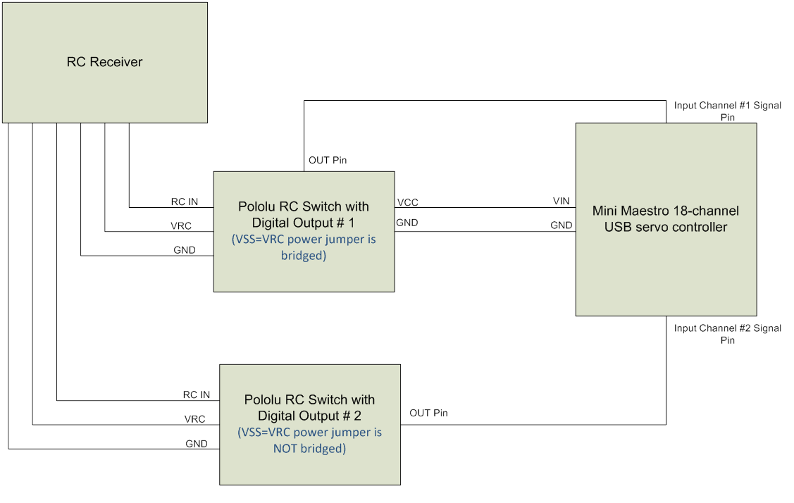
I think I’d rather play it safe and avoid brownouts and keep the servo and logic power separate. My configuration also includes a minimum of two “Pololu RC Switch with Digital Output” switches. One for the landing gear extend and retract operations and one for the cargo bay door open/close operation on my C-130. I’ve read the Pololu RC Switch with Digital Output switch and Maestro 18 documentation and I think I have it figured out, but I’d like confirmation before I proceed. Here are my assumptions as well as a wiring diagram:
Maestro servo power is provided by a SBEC(6V) with VSRV=VIN NOT bridged.
  On RC switch #1 the VSS=VRC power jumper is bridged in order to supply power from the RC receiver to the RC Switch and the Maestro processor. The power wire from the RC Receiver is also connected on VRC pin of the RC switch.
      a.)       Assumption; because the power jumper is bridged on the RC switch and the VRC pin is receiving power from the receiver,  the switch recognizes that it is to receive power from the RC receiver power lead and provide power to the Maestro processor via the VCC/GND pin on RC switch and the VIN/GND on the Maestro 18.
      b.)      Question/Assumption: On the Maestro 18, one channel is configured as input. This channel will only have ONE wire connected to it which is the signal wire. The single connection is the “OUT” pin on the RC switch to the “Signal” pin of the selected input channel on the Maestro 18. Is this assumption correct????
On RC switch #2 the I’m not sure where the RCS switch is powered from. Is it powered via the RC Receiver with the VSS=VRC power jumper NOT bridged? Also would my assumption on point #2 be the same with regards to the “OUT” pin on the RC switch to the “Signal” pin of the selected input channel on the Maestro 18?
Powering the Maestro from your RC receiver by bridging the VCC and VRC pads on RC switch #1 should work. However, you should also connect the VCC and VRC pads on your second RC switch, since VCC needs to be supplied with power for the board to work. If you connect things the way your image002 schematic shows, bridging VCC and VRC on the second RC switch will power the switch from your RC receiver.
In general, all electronics in a system should share a common ground. So, because your switches and Maestro are being powered by your RC receiver (i.e. the ground node on the receiver is shared between all those devices), you can get away with only connecting the OUT pin to the Maestro in order to read it. However, adding the GND connection between the second RC switch and your Maestro will not damage anything.
Also, I suspect you understand this, but just in case it was not clear: you will need a separate input channel on the Maestro to read each digital output from the RC switches (i.e. you would need a total of two channels like your schematic shows).
I’ve finally had time to write the code for my project and it works . I would like to back the continuous servo off the limit switch after the limit switch has been closed. Is this possible with continuous servos and if so what command options are available? For example can I send a command to the continuous servo to rotate 1 rotation in either direction?
Continuous rotation servos do not have position control like standard servos. Instead, the standard hobby RC servo signal relates to a rotational speed. So, to get your continuous rotation servo to rotate a certain amount, you could send a servo signal (e.g. 1.8ms) for a specific amount of time, and then send the signal to stop the servo from rotating. This is not a very accurate rotation, but it sounds like it could be useful enough for your application. If you need more position accuracy than that, you would have to add some other hardware for external feedback, like another limit switch.

 . I would like to back the continuous servo off the limit switch after the limit switch has been closed. Is this possible with continuous servos and if so what command options are available? For example can I send a command to the continuous servo to rotate 1 rotation in either direction?