
Hi, I am using this Pololu G2 High-Power Motor Driver 18v25 motor driver to drive a DC motor. I am unsure if the value that I am getting from my current sensor is correct as it is giving 0.0007A when it is high and 0.0004A when it is low. This is using NI Labview with NI 9219 card with the current configuration. It states that this is computed from the voltage that the ADC measures across an internal shunt resistor. While using the voltage configuration, I am getting a value of 2.5V low and 3.5V high. I have all of this hooked up to a breadboard with the motor driver using arduino pins to connect to the NI card. Is this what I should be expecting from the CS?
Hello.
I am not familiar with your NI board, and it is not clear how you are using it to measure the CS pin, but neither the current values nor the voltages you provided make sense. As described on the motor driver’s product page under the “Current sensing and limiting” header, the output voltage on the CS pin should be about 10 mV/A plus a small offset, which is typically about 50 mV.
If you want to confirm the CS pin is working, my suggestion is you remove the NI board from your system and just try monitoring the CS pin with something simpler to use like a multimeter, an oscilloscope, or an analog input on your Arduino. Ideally, I recommend monitoring the CS pin while a known load is connected to your driver outputs (e.g. a programmable load, an appropriate power resistor, or even a motor whose current is simultaneously monitored through some other method, like a current probe or multimeter).
- Patrick
Hi Patrick,
I used an oscilloscope and the signal is extremely noisy and has an offset of ~0.023V. I subtracted it out and ran the motor and I’m seeing about ~1A and the signal is extremely noisy. Is a noisy signal expected? What is the output voltage range of the current sensor?
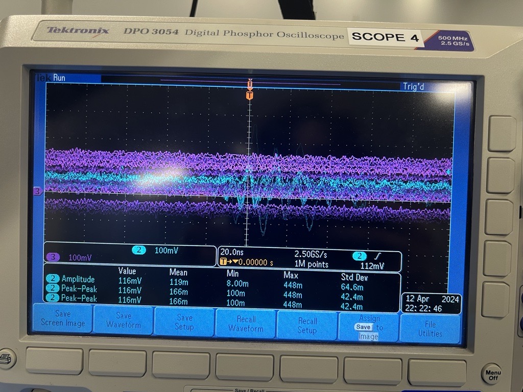
The blue line is the CS pin and the magenta line is the current probe.
Thank you.
I generally expect the current through a DC motor to be a noisy signal, but there are a few immediate issues that I noticed with your scope setup. First, you said that magenta is a current probe measurement, but it seems to be reporting a measurement in mV, rather than mA or A. Can you post more information about the probe you are using?
Second, it is probably going to be difficult to gather useful data from looking at these signals with a 20ns/div scale. My recommendation would be to start out with a scale that would let you capture the square wave of your PWM signal, and then work from there (and if you have another signal channel available on your scope, adding the PWM signal or one of your motor output signals can be a useful reference to see what is going on). For example, most of the pins on an Arduino Uno will output a 490 Hz PWM signal by default when you use analogWrite(), so starting with a scale around a few milliseconds per division might be a good starting point in that scenario.
Can you share more information about how you are testing the driver, like how you are powering it, what motor you are using it with, how you are generating your PWM signal (its duty cycle and frequency), and what you expect the current draw to be? Additionally please post some pictures of your setup that show all your connections to the board and how your scope probes are hooked up.
- Patrick
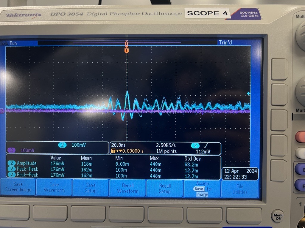
First, you said that magenta is a current probe measurement, but it seems to be reporting a measurement in mV, rather than mA or A
We’re using the current probe that measures 100mV/A
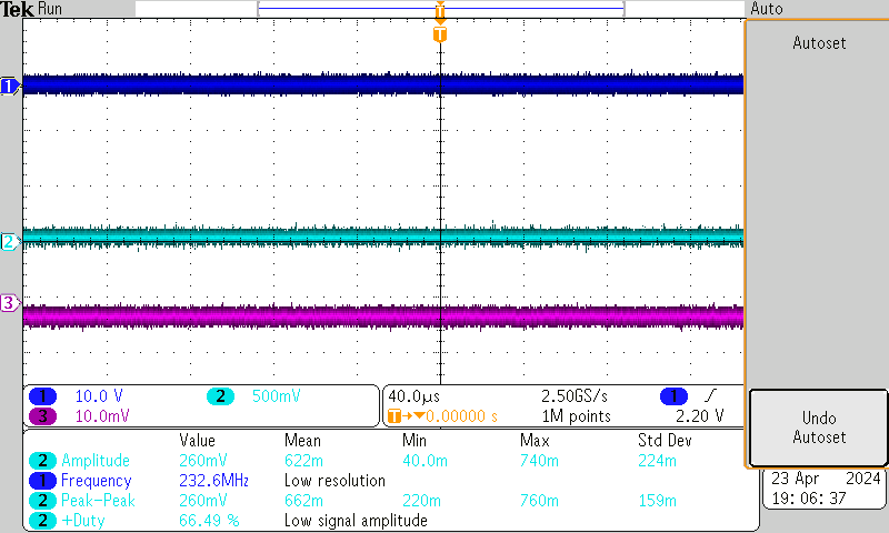
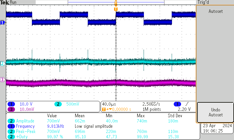
Purple represents the current probe which is now measuring 10mV/A. Light blue represents the CS. Dark blue represents the PWM.
The PWM is being generated by an NI digital output card (NI 9401) with a 50% Duty Cycle with a frequency of 10,000.
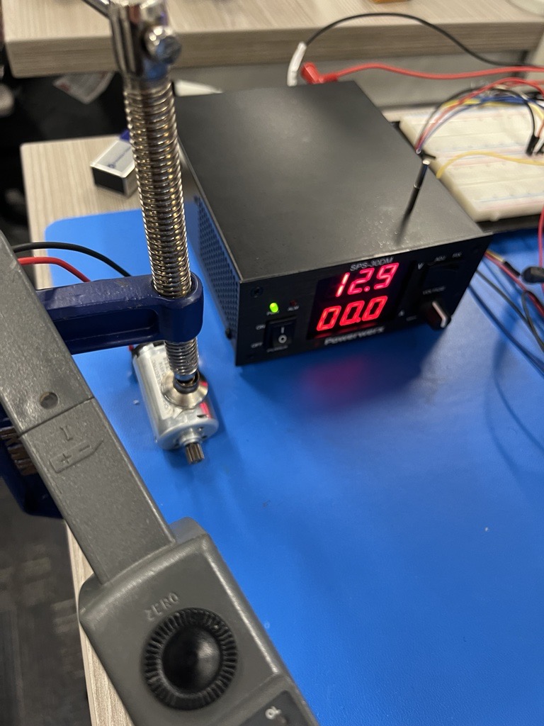
We are using a Johnson Electric 12v Motor powered by an external power supply.
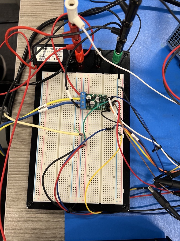
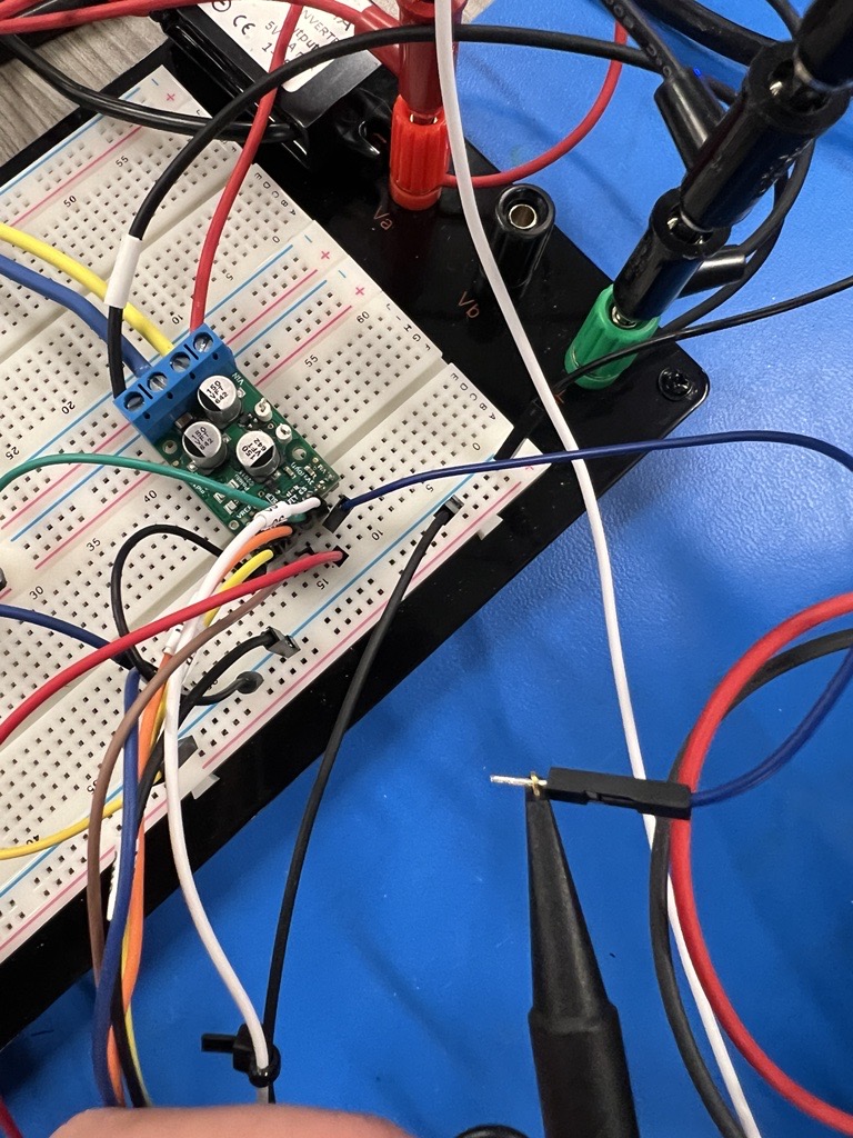
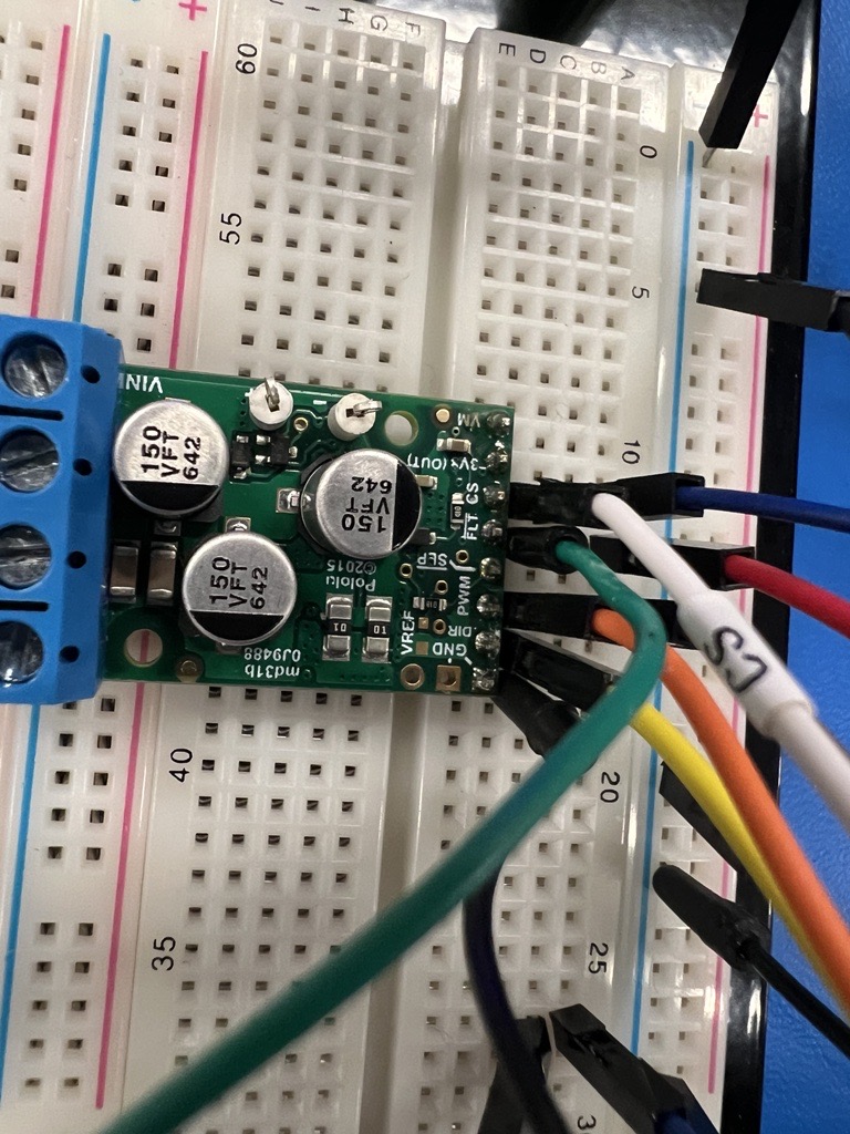
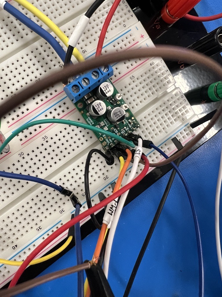
Legend for all of the wires connected to the motor driver:
- White wire represents the current sensor going back to analog input
- Green wire is connected to the fault pin jumped from a 5V input
- Orange is connected to the PWM sensor going back to a digital output. I have my probe also connected to this pin
- Skinny Yellow wire is the directional pin
- Black wire is the ground coming from a common ground going back to the power supply
On the other side of the motor driver I have:
- Red wire going back to the 12v PS
- Black wire going back to the common ground coming from the 12V PS
- Yellow and Blue wires going back to the 12V Johnson Electric motor.
I’m also using a 12V to 5V buck converter to power an external actuator as well as powering my fault pin.
Though your wiring is a little messy and hard to follow, your connections generally look okay.
Your current probe measurements suggest that your motor is drawing very little current in your current setup. For that type of condition, the CS pin behavior matches up with what I would expect. The output is generally looking stable except for the brief spikes corresponding to when the H-bridge switches (which might not be practical to actually catch depending on your microcontroller). Keep in mind the CS pin’s resolution is only 10 mV/A, so it probably would not be practical to use it for measuring very low current draws with meaningful precision.
If you can add a substantial load to your motor so that it draws a higher current, that might be a better way to see how the CS pin behaves. Alternatively, as I mentioned in my first post, a programmable load or some appropriate power resistors might be useful for this.
- Patrick