
Hi,
question about the current sense pins (CS1, CS2) on the SVP-1284. I have 2 identical motors with the same settings running and try to use the current sense pins to measure torque. CS1 = 6mV and CS2 = 20mv. I tried switching motors around with the same result. Somehow CS1 is always lower. Any idea how I can get them to show the same value? Is there a way to calibrate them?
Thanks
Hello.
I think it’s just not very practical to accurately measure such small voltages/currents with the SVP’s current sense circuit and ADC (the ADC only has a resolution of around 5 mV/count in 10-bit mode, and the two least significant bits are probably mostly noise), and in an absolute sense, you are talking about almost negligible differences. Can you try repeating the test with higher currents?
- Ben
Hi Ben,
I tested the system with a larger motor again and found the following data:
For testing I use a DMM.
M1 = 50mV with no-load and 558mV with the motor stalled.
M2 = 102mV with no-load and 610mV with the motor stalled.
Retesting the motors I can use showed this data:
M1 = 2.8mV with no load and 24.2mV with the motor stalled.
M2 = 33.2mV with no load and 70.7mV with the motor stalled.
The 33 to 70mV could work with around 8 steps (8x5mV) from no-load to stall.
I also could put an amplifier in line with a way to adjust the output voltage to calibrate M1 to M2.
A little bit about the application, I am building a life-cycle test fixture and like to read out the torque every x cycles to see changes over time relative to motor position. The motors I use are Faulhaber with a quad encoder and gearbox. I have 12 SV-328 for a similar fixture already running but I can’t capture the current on the motors.
-V
I suggest you perform a controlled test to better characterize how the current sense voltage relates to the current, which in turn can help you calibrate for any differences between the two channels. For example, first use your multimeter in series with your motor to measure its stall current, and then use it to measure the current sense voltage under the same conditions (i.e. with the motor stalled). Maybe you can get a few data points for each motor channel, which should provide a better sense of what is really going on.
- Ben
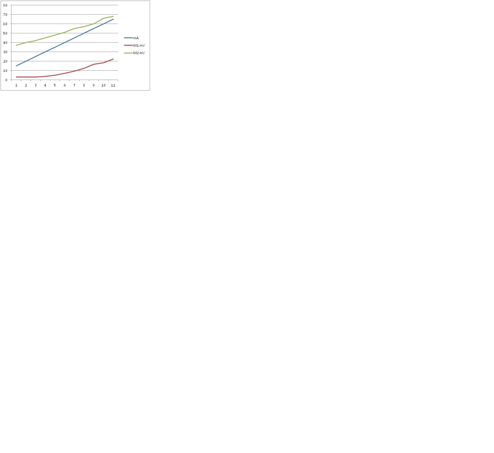
I used 2 meters, one in line with the motor and the other on the current sense.
Data points where taken every 5 mA on the motor current, ranging from 15 to 65mA
The attached picture shows the difference, data points are not perfect due to torque variations.
-V
How were you controlling the current? Can you use your higher-current motors to see what happens over a wider range?
- Ben
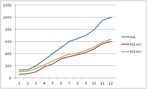
I have a clutch system on the motor shaft to adjust the break force from no-load to stalling. One DMM measures mA on the motor, the second DMM mV on CS1 or CS2. I adjust the clutch to different mA values and record the corresponding mV.
I did a test with a 1A motor (see graph) the average deviation was 36mV between M1 and M2. It never gave me 850mV for 1A either. I guess that’s the tolerance between the 2 current sense channels. If this is the case, I have to find a different way to measure low current flow on the motors for this project.
The sensors on the SVP are not intended for accurately measuring very small currents (that is not the typical thing you care about when using motors). I think you should either try using the data you just got to calibrate your current readings, or you should look into getting/making a more appropriate current sensor.
- Ben