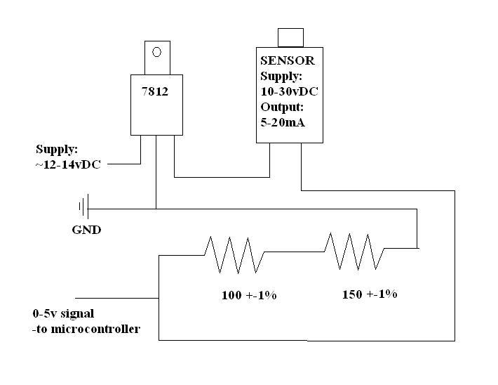
I have a pressure transducer that outputs in 5-20mA for the pressure scale that it reads and I converted it to a 0-5v signal with a simple circuit. The problem is I think it’s too simple.
I wanted to be able to input this signal into a microcontroller I have logging several things and needed a 0-5v signal for one of its ADC lines. Well all I pretty much did was put a voltage regulator powering the transducer and then used a 100 and a 150 ohm resistor in series to give 250 ohm to convert 20mA to 5v. So V=IR, 5v = 250*.020A, 1.25v = 250*.005A. This worked fine and I was able to calibrate the sensor but there is a lot of noise on the line. Depending on what is going on with the power this circuit is getting I will get wild fluctuations in the signal. I’m thinking some filtering capacitors would be a good thing here but I do not know what size and type I should use and where to put them. Across the power? Across the signal out to ground? I am attaching a crude schematic of how I have it arrainged now and would greatly appreciate any suggestions on capacitor placement and type. Also, should I have a zener diode in the circuit too? Maybe a 5.1v zener?
Can you post a link to your sensor data sheet? You should almost certainly have some capacitors around your voltage regulator. Do you have access to an oscilloscope? That would help you determine the effects of different capacitors. I would put something like a 0.1 uF ceramic and larger (47-470 uF; more shouldn’t hurt) electrolytic across the output, and depending on your power source and wire length, something similar on the input. The power caps should just affect the noise; a cap on the output will help but reduce noise but will also slow down legitimate changes to your sensor output. Your current is kind of high and the resistors kind of low, so you’ll need something that’s at least a few uF to make a noticeable change.
If you’re concerned about the voltage going past 5V, why not use 200 ohms instead of 250?
I have a 5-20mA output one. Let me know if you need the full part number from my particular transducer.
Also, let me give you a better understanding of my application. I am using this to log fuel pressure on an automobile. The engine managment computer has the capability of logging many different variables and extra channels can be used if they’re 0-5v signal range. So, as you might expect the environment in a car can be pretty noisy electrically: high levels of EMI from high voltage ignition sources, DC motors everywhere, etc. I particularly see a large fluctuation during cranking when the voltage can dip probably as low as 8-10v depending on the charge of the battery. I’m basically pulling the power that goes to that 7812 regulator directly from the main switched supply for the whole vehicle.
At home I have an anchient LCD(think calculator…not laptop) oscilloscope that I could use. Measurements are a manual operation on this thing but I would at least be able to see spikes provided it has a fast enough sampling rate. I could use a nicer one from work though.
Responce from the sensor isn’t super critical. My trainsients shouldn’t be super quick…on the order of tens of miliseconds I would think.
The wire lengths between my sensor and this little module that houses my regulator and resistor board are on the order of 18"-24" or so. And a simular length(probably more like 12") is from the module to the datalogging device. They’re all 18-20AWG wires.
So the 200 ohm would just change my scale then(1-4v)? I guess I’m just worried about protecting the ADC input to the micocontroller in case something decided to go haywire(like the sensor suddenly pulling a ton of current or something). I’ve seen simular 5.1v zeners on the other inputs but didn’t know if it was for protection or not.
Does the voltage rating of the capacitors matter? Is there anything wrong with too big of voltage rating if I can’t find something smaller?
The capacitor voltage rating should be higher than the highest voltage you expect across the capacitor. For 12V batteries, the caps should be rated at least 25V. Higher ratings won’t hurt; the capacitors will just be bigger and more expensive than lower-voltage versions.
The zener shouldn’t hurt. Just make sure it can handle the power it will need to dissipate in the over-current condition.
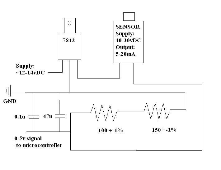
Just to make sure I’m understanding correctly, here is another schematic with added capacitors on the output. Is this the output you were referring to(the output to the ADC)? As far as the input do you mean the input voltage to the regulator or the input voltage to the circuit which is the output of the voltage regulator?
Oh, and also, for the electrolytic, do you mean a polarized version? Or not?
Sorry, that’s not what I meant. The two caps you have there are what I meant to suggest for the voltage regulator output, the regulated 12V. A polarized cap is fine, just make sure you don’t put it in backwards. However, you might also want to use that 47 uF on the signal output, and add something to the input side of the regulator (take a look at the 7812 datasheet to see what is recommended for that regulator).