DevC++ is a C and C++ compiler, when you create a project you select what type of program you’re going to make. Also, since C++ is somewhat of an extension to C, code written in C should compile as C++.
Yes, you should break the header pins into 3 lines to fit the holes. You may have to do something similar with the servo-controller pins (unless yours was pre-assembled).
You are correct, you will not be using all of the pins on your servo controller, you don’t have to worry about ones you arent using.
And the blue thing is a jumper, a cap that connects two pins together. If it comes installed you can just pull it off.
Im leaving tomorrow (saturday) to Greek so i wont post any messages for at least a week (if i find a internet cafe or something then maybe) So when i come back i should have recieved the servos.
One last question, i hope ure able to answar it before i leave:
Im right that both the servos and the servo controller needs power.
Servo power: 2 pins up right corner,
Servo controller power: 2 pins lower right corner…?
In the image I posted before, the servo controller power is in the bottom left corner, which is what you probably meant, but this graphic should make it 100% clear.
Remember, if you connect the servo power and controller power (using the Vcc=Vs jumper) you don’t need to connect another power source to the controller power pins!
Anyhow u mean if i connect a power source 6V to the two holes without any pins in it, it be power for the servos and the servo controller? But if i dont i will have to attach 2 power sources: 1 in the upper right corner and 1 in the lower left?
And u said i would have to remove the blue jumper, i just tried it, i thought u meant also remove the pins underneeth but that won’t be necessary right?
Plz respond in the end of the day, im leaving this night…
No, if you want to run the controller off of the servo power (which you should ONLY do if your power source is less than 5V), you should connect those two holes to each other. So, your options are:
Yay for clip art!
And yes, you only have to pull the blue jumper off, you don’t have to remove the pins underneath.
At the second picture both the servos and the servo controller runs on 1, eks: 6V battery pack so wouldent it perform much worse and go empty of power much faster then if i added power to both places (picture 1)?
If you dont respond within a couple of hours i wont see this before i come home, but not hurry anyway, i havent got my servos yet anyway.
I have also decided to bring a bit of the PDF file from parallax: “whats a microcontroller”
So before i leave i just want to say im really thankfull for your help!
The servo controller itself takes very little power, so it won’t make a big difference in the life of your batteries. The problem is that the Vcc=Vs jumper bypasses the on-board voltage regulator, so you should only use it if the voltage of your battery is below 5V.
I’m sitting in a internet cafe at paros in greece right now paying 1,50$ for 30 minutes at the computer…
So i cant stop thinking about coming home and trying out the electronics and the code for my robot, i have soon read 3 chapters at parallaxes “whats a microcontroller” and i just finished the chapter with the LED and how to connect them to parallaxes microcontrollers. I think i have decided to try the parallax “homework board” or “Board of education” when I’m done with what im doing now. It
looks really easy to use and the guidence is for newbies not pros, they explain everything in details. And there’s a board where you can wire up ure own circuits like LEDs or whatever and it had a USB input already wired on it. Do you think this is a good choice for me?
Im also learning a lot of BASIC coding that i can use with the BASIC stamp “homework” board. But at the board you have to make your own I\O pins (i think) couse i have seen pictures of them and looks like the place where the Pololu product have I\O pins the BASIC stamp “homework” board have empty sockets.
You might noticed i have learned some new words like what I\O (input\output) and sockets is.
I think that was about what i was going to tell\ask about.
Now im going to keep on bathing and reading about BASIC programming language, maybe i’ll drop by a internet cafe a little later to see if you have responded if not i will see it when i come home, you keep on having a good holiday (so i hope) and i’ll talk to you later! BYE
The Parallax Board of Education or the Homework Board would be a great way for you to get started with microcontrollers.
When we call something a “Pin” though, we don’t litterally mean you have to have a metal pin sticking out for it to work, it’s just a term for a point of connection to a device.
Both the BOE and the Homework Board bring the I/O lines (pins) out to sockets, rather than actual pins, but this is actually a good thing for you. You can just press your electronic components into those sockets, or into the “breadboard” socket grid (no soldering involved) to connect them. This way it’s really easy to experiment and fix mistakes.
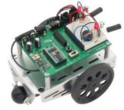
Remember the picture of the BOEbot? If you look closely all the added components and wires to make the robot run are pressed into the sockets, with no solder!
Yeh i see, i think i will go for the homework board when im done with the robot im making right now (going to make when i get home)
It looks so easy with the breadboard included on the homework board couse i can make my own circuits like LEDs and so on!
When im coming home i will start connecting servos to the microcontroller and start bulding the chassis of the robot, i got to admit the microcontroller from Pololu i ordered is so much smaller then what i thought.
Cya
Edit: I looked at the buttom of the page for the micro servo controller i have ordered (and recieved) and it says this in yellow:
Note: The Pololu micro servo controller is available fully assembled, or as a partial kit that requires soldering of the through-hole male header pins, which are included in the kit. To use the micro servo controller in robotics projects, you need to connect it to your own servos [size=200]and robot controller[/size].
You said i could connect the Pins on the servo controller directly to the servos, why do i then need another robot controller?
Edit: I thought about my questions and i relized you have already told me the answar before, i only need the robot controller if i dont want the robot to be connected to my computer at all time!
OMG i cant use the code you sent me with the devcpp.exe software, i try to run but it says i have to compile it, so i try compile, but it’s something wrong with every line of the code, eksample of when i started compiling:
(this is without edditing anything to the code)
1’st wrong:
return;
35 C:\Dev-Cpp\Examples\FileEditor\Untitled1.cpp return-statement with no value, in function returning ‘int’
UPDATE: i removed every return; command in the code and tryed again, this made the compiling finished and it was ready to run, while i soldered the batterys and all of that to the servo controller we made a bit mess on 2 of the servo 0 I/O pins and 2 of the servo 1 I/O pins. Still i tryed to attach the servo onto it, allthough the servo dident go as far down on the pins as it did on the pins witout any mess on it i tryed them. I ran the program and a red LED glowed on the USB to serial adapter and a yellow LED glowed on the servo controller, a black window opened with availebility to press eks: A to get servo 0 to a position, lets say 3300. Still even if i pressed the buttons nothing happend with the servos, i think i read somewhere that the yellow LED indicates that the servo position is out of range.
Glad you figured out how to compile the code. Source code doesn’t run as a program on its own, its just a set of instructions for how to build a program that will do what you want.
Looking at my code more closely, there is one somewhat improper return function (still compiles and runs fine for me), but for the most part the return functions are necessary to the proper functioning of the program! Here’s a slightly fixed version of the source code. This compiles and runs correctly for me, so you shouldn’t make any changes to start, except for the com port number (if you’re using a com port other than COM1).
If you get error messages from DevC++ when you try to compile this code with no changes, there is probably a bad compiler setting somewhere. Try starting a new project (file–>new–>project) and selecting “Console Application” and “C Project”. Save it somewhere and copy-paste the original code over the example code in the “main.c” file it creates for you.
The yellow LED on your servo controller means that it is powered on and is waiting for instructions, but hasn’t received any (without return lines, the program wouldn’t be able to open a serial port). If the servo controller receives a good signal from the computer, the yellow LED will go out, and the green LED will flicker as you send new signals. A flashing red LED is the signal that something bad has happened.
This is my situasion right now:
Im sittin here with all the wirering in front of me: all batterys connected, and the USB to serial adapter attached to the micro controller, the USB to serial adapter is also connected to the computer’s COM port. The USB to serial adapter’s LED is glowing red and the micro controller’s yellow led is lightning. i have 3 servos connected, one at I/O pins 1, one at I/O pins 2, and 1 at I/O pins 7. I tried to compile and run the new code you sent me and it worked, nothing wrong with the code itself, but nothing happend with the servos!
Great that you got it to compile and run! This is a big step!
The yellow light means that no signals are being recieved still, so something is not right. Does the software take you to the “Press a key to move the servos” menu, or does it say something about a com error? One guess is that the program is trying to use the wrong com port.
You can check which com port the USB to Serial adapter is using by going to the device manager (in XP right click on “My Computer”–>“Properties”–>“Hardware”–>“Device Manager”) and opening up the “Ports” list. One of the devices on the list should say:[ul]Pololu USB to Serial Adapter (COM1)
or
Pololu USB to Serial Adapter (COM3)[/ul]or something like that.
Lets say, for example, your USB to Serial adapter is operating as COM3. You would need to change one line in the code [ul]from:
comPort=openPort(1);//PUT YOUR COM PORT NUMBER HERE!
to:
comPort=openPort(3);//***PUT YOUR COM PORT NUMBER HERE!***[/ul]
Also, you might try to move your servos with the slider program I sent you a while ago, just to see that you have the right port number and everything’s wired up right.
Here’sthe update:
I did what you said and checked the COM port number, it was COM5, so i changed the number…IT WORKED!!
The servos changed the position at once and i got a window where i could press different buttons and the servos did move some degrees at every button press. Then 2 wires i had soldered had physical touch and the servos stopped working, a red LED flashed, then i knew something was wrong. I fixed the soldering problem, but still it dident work, so i changed the Current flow for a cupple of seconds and so changed it back
(from 6V to 9 and then back to 6)
It woorked… Everything is just fine now and it really worked…
I think this is, maybe, my last post on this topic except when i will post the final result.
So my question is: Do you/ Pololu company have any special way you solder the battery to the microcontroller or something like that, couse i see the pololu microcontroller have perfect soldering result and im having difficultys with getting to big pieces of solder iron!
Do you have any links withy solder package that can give a little better result?
And i wanna say that without your help i probably woulden’t come this far, and you have also helped me out in the robotics world, now i have more experience for my next robot, THANKS!