Hi.
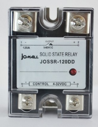
I need assistance controlling a single phase solid state relay switch as seen in the picture attached.
The relay controlling a 6S/80A Lipo battery as a cut-off power switch to the ESC, relays are powered by 2 wires only (+ -), 0 for closing a circuit and a certain voltage to open it (or the other way around - doesn’t matter).
My question is how can i control such relay from a port on the Maestro board that does not have the signal pin (white wire)?
Thanks.
Eran
Hello, Eran.
Under the “Channel Settings” tab of the Maestro Control Center, you can switch the mode of one of the Maestro’s channels to “output”, which will allow you to control whether the output is low (0 V) or high (VCC). (You can learn more about how to do that under the “Channel Settings” section of the Maestro’s user’s guide, which you can find under the “Resources” tab of any Maestro’s product page.) You could then connect that channel’s signal to your relay to activate it. However, the Mini Maestro’s outputs can only provide a few milliamps of current, so you should first measure the amount of current that your relay requires to turn on to see if the Maestro output can handle it. If the Maestro’s pins cannot provide enough current, you would probably need to add a FET to control the relay like we do on our relay boards. You can find a schematic that shows this on the bottom of one of our relay board product pages, like this one. If you are not sure how to add your own FET, you might consider using something like our RC switch with small or medium low-side MOSFET, which can take a standard RC signal (like what the Maestro generates), and turn on and off higher-current loads.
-Jon
Thanks Jonathan!
Thanks for your comment, I just verified it with a low volt led and it is working.
The thing is that I want to use as few parts as possible or have 1 single devise that does the switching for me instead of doing soldering or use additional connectors, My motor draw ~80Amp at 22.2v I am scared to play with low current relays and add a MOSFETs…
The SSR i pointed (picture attached) will do the job and in order to operate the switch - it can take 4v at 15mA to open or close the switch so when it comes to use the Maestro voltage to operate this unit like you recommended - I don’t see any issue, is this correct?
Thanks,
Eran
The Maestro’s signal pins have a total current limit (in or out) of up to 60mA each. But if powered from VIN, the Maestro’s onboard regulator will only be able to provide about 20mA (it is a 50mA regulator and the processor on the Maestro takes about 30mA). So, if you do not plan to draw current from many other signals pins, or if their current draw is basically negligible, you could likely devote a single channel to triggering your relay. (You can learn more about these limitations under the “Micro Maestro Pinout and Components” section of the Maestro’s user’s guide.)
-Jon
