Hello, We are very new to 3pi and also to electronics in general, so pardon if any question is silly.
Background:
We bought following items, and the goal is to attach three distance sensors to 3pi all the while making sure the line following function of 3pi remain intact. IMPORTANTLY, we do not want to attach distance sensors & their connections directly to 3pi but only onto the expansion set (which in-turn is attached to 3pi), and preferably we want to keep LCD also connected to 3pi. (worst case, i.e. if no other option at all, then we can remove LCD).
Items:
3pi: https://www.pololu.com/product/975
Expansion Board: https://www.pololu.com/product/979
Distance Sensors: https://www.pololu.com/product/136
Question:
We want to understand a few things:
- What are the connections required (i.e. what wire of distance sensor should attach to what point of the expansion board) for all three distance sensors? A diagram or picture will be very appreciated.
- We have attached the expansion board with 3pi using items provided with the expansion board. Do we need any more connections between 3pi and the expansion board so that sensors can be attached to the expansion board such that it in-turn connects to 3pi? (likely yes. in that case what more items and what more connections between 3pi and expansion set is required?).
- As far as we understood, the distance sensor we bought is ‘analogue’ sensors and our purpose is also to measure the distance. So, we believe we need to connect the sensor only to the analogue points of the 3pi (and not to the digital points) correct? Please answer Q-1 accordingly.
Options:
If there is no solution to this problem with three analogue sensors, by keeping LCD also attached, there are few options we can think of for a different kind of solution:
Option-1: We can remove LCD
Option-2: We can replace one sensor for digital sensor (instead of analogue)
Option-3: Any other option if anyone can think of?
Note:
A) We have already looked into this: https://www.pololu.com/docs/0J26 , but being a novice it is not bringing us a clear idea from two point of views: (1) We need to attach three distance sensors, not two. and (2) We need to attach our sensors to the expansion board, not directly to the 3pi
B) We also have already looked into this: Connecting three Sharp digital distance sensors , but that is also not providing us clear idea because (1) it explains using digital distance sensors (while we have analogue distance sensors), and (2) it explains using m3pi expansion set while we have a normal expansion set (not m3pi).
Your help will be appreciated.
Many thanks in advance,
–Team AIRO
Hello,
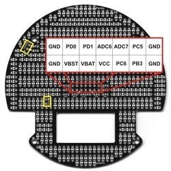
As shown in the “Pin Assignment Table Sorted by Function” in the “Pin Assignment Tables” section of the “Pololu 3pi Robot User’s Guide”, you can free up three analog pins by removing the three jumpers shown in the “Specific features of the Pololu 3pi robot, top view” picture.
Since the 3pi Expansion Kit with Cutouts is basically a prototyping board shaped to the 3pi form factor, where you mount those sensors would be totally up to you. Please note that the 3pi Expansion Kit does not have any special logic for communicating with the 3pi base, so you will still need to connect your sensors to the 3pi itself or add some other microcontroller to process those signals. If you post a wiring diagram of your proposed connections, I would be glad to look it over.
-Derrill
Hello,
Thank you. This helped in bringing clarity up to many extent. We have a couple of follow up questions to make sure we are doing it correctly.
Question:
- You mean to suggest to use these pins correct?: PC5, ADC6, ADC7
- The Pin Assignment Table pretty much clarifies it, but being novice we want to ask you that by removing jumpers to use pins PC5, ADC6, ADC7 to attach our distance sensors, are we going to lose any functionality of the line-following? Especially losing AD7 (user trimmer potentiometer) will cause any problem with the line-following function?
Just to clarify, what we meant by attaching sensors to the Expansion Board and attaching Expansion Board to the 3pi is this:
- We are already following this direction to attach Expansion Board to 3pi. https://www.pololu.com/product/979
- That exposes many pins onto the Expansion Board, where we can connect our sensors (i.e. on the Expansion Board). See picture ‘Solder connections for male headers on the 3pi expansion kit with cutouts’ in https://www.pololu.com/product/979
- If we need to use pins PC5, ADC6, ADC7, then it is clear that they are exposed on the Expansion Board which we can connect our sensors to.
Our original question about if any further connection between 3pi and Expansion Board was required or not, was based on a doubt that if we were to use any pin which is not exposed to Expansion Board (is there any such?), then we might first need to expose it to the Expansion Board by making any extra connection between 3pi and Expansion Board.
But now, we are clear that we don’t need to do that -since the plan is to use pins PC5, ADC6, ADC7.
Regards,
–Team AIRO
Using the PC5, ADC6, and ADC7 pins your line following should not be affected. You can access those pins on the expansion board when you connect the expansion board to the 3pi via the extended header pins shown below without additional connections to the 3pi.
-Derrill
