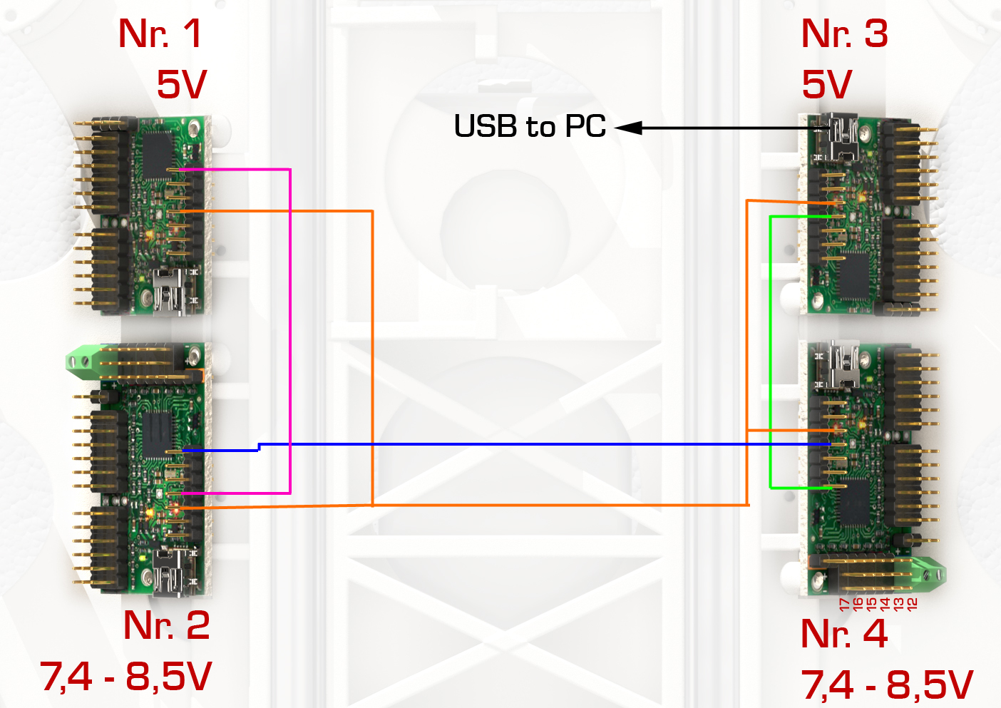
I need to connect 4 maestro boards in a daisy chain. Attached you will find the wiring diagram.
(I use 2 boards for 5V servos & sensors and 2 boards for 7.4V servos.) Board #3 is the one connected to the PC.
All boards are set up with serial mode “USB Chained”.
Talking with board #3 is no problem. The other devices are not reachable for my scripts. Only at board #3 the green light is on. At the other boards the yellow one is flashing. After power on or after the first command the red error led is on. Sometimes on board #3 sometimes on the other boards (all together).
However - to locate the error I would like to know, if the wiring is ok so far?
Only the Maestro whose USB connection you are using should have its serial mode set to “USB Chained”. The other three Maestros, which are slave devices, should have their serial mode set to UART. Also, it looks like you have your wiring mixed up. The Maestro that you are sending commands to via USB (i.e. the master device) should have its TX pin connected to all of the other boards’ RX pins. Then, starting at the farthest board from the master, you should have the TX pin connected to the TXIN pin of the next Maestro in the chain. When you reach the master device at the start of the chain, the connection from the TX pin of the previous board should be made to the RX pin of the master. More information about daisy chaining, including a simplified wiring diagram, can be found in the “Daisy Chaining” section of the user’s guide. Please note that along with these connections, all of the boards will need a common ground.
By the way, are the Maestros in your pictures 3D renderings? What program did you use to make them?
ok, thanks for your detailed answer. Apparently I misunderstood many things…
One thing could be a problem. I use a BEC like this…: der-schweighofer.at/artikel/ … ?query=bec …to get 5V from 7.4V. I’m not sure, if it’s possible to connect the ground from input & output together. I have to check.
Concerning 3D: I’m using 3D-Studio Max. (I’m developing an octopod. The parts are printed at shapeways.com so I need to build everything in 3D. As I’m using MAX since the early beginnings I’m using this software. Actually one should use AutoCad or something similar… Here you can see some old works: ilumi.de/projekte/3d_visualisierung/ )
I am glad you were able to get it working; thank you for letting us know. Please feel free to share your project in the “Share Your Projects” section of our forum. It sounds really neat, and we always enjoy seeing what customers make with our products!
I’m afraid there is still a problem talking to the last board in the chain.
Attached you find the new situation of wiring. As you see, the chain starts at board #3 → #4 → #2 → #1.
After power up the boards and PC (beaglebone black) the yello LEDs are slowly flashing on all boards.
After sending a command to board #1 (set target of one servo) the red LED turns on. Also it’s not possible to read the error from this board - by reading the 2 Bytes the script runs in a timeout - that means nothing comes back or even the “getError-Command” doesn’t reach the board.
To read the error I disconnected the TX & RX from this board an used an USB-Cable to connect to a windows PC. The Maestro Control Center returns error 0x0011:
Serial signal error
Serial protocol error
After clearing the error I was able to move the servo as expected by the Control Center. Also I could read values from 2 attached sensors. So the board seems to be ok.
The other boards are working well. I can move servos & read sensors. That means, my code should be ok too.
Is there still somethin wrong at the wiring?
By the way - what is the preferred Baud Rate for this setup? After reading page 68 of the manual I used 115200 - or should I use slower rates?
Could you try disconnecting board #1 in your setup and swapping it with a board that is working correctly, such as #2? If the problem stays at the same location (board #2 receives an error), then the problem is most likely with your connections. The connections in your diagram look correct, so you should double check to make sure that your physical connections match your diagram.
If the problem follows the board, then there might be something wrong with the settings of the board or your code. In this case, you could then try swapping the device numbers as well, which should narrow it down to either the code (if the problem changes with the device number) or the board settings (if the problem stays with board #1).
I would expect a baud rate of 115.2 kHz to work fine for this setup. If you are concerned that this might be the issue, you might try lowering it.
The boards are all working now! After fumbling at the wires a while all boards were working as they should. So I guess it was a loose connection.
Now I soldered all daisy-chain-connections and the problems didn’t happen till now.

 Here you can see some old works:

