Goodnight!!
I have a problem with the programming for my white line follower in black background, the problem is in my code since it is not giving me results and I ask for your support to help me out of this hurry, then I show you the code and the Follower data to help me please, I would greatly appreciate it.
Previously I was using qtr8a sensors and the line follower worked, the problem was when I damaged my analog sensors and unfortunately I did not find the same ones and replace them with qtr8rc (digital) and I thought the programming would be simple to change, but for I have become a mess since the follower does not work.
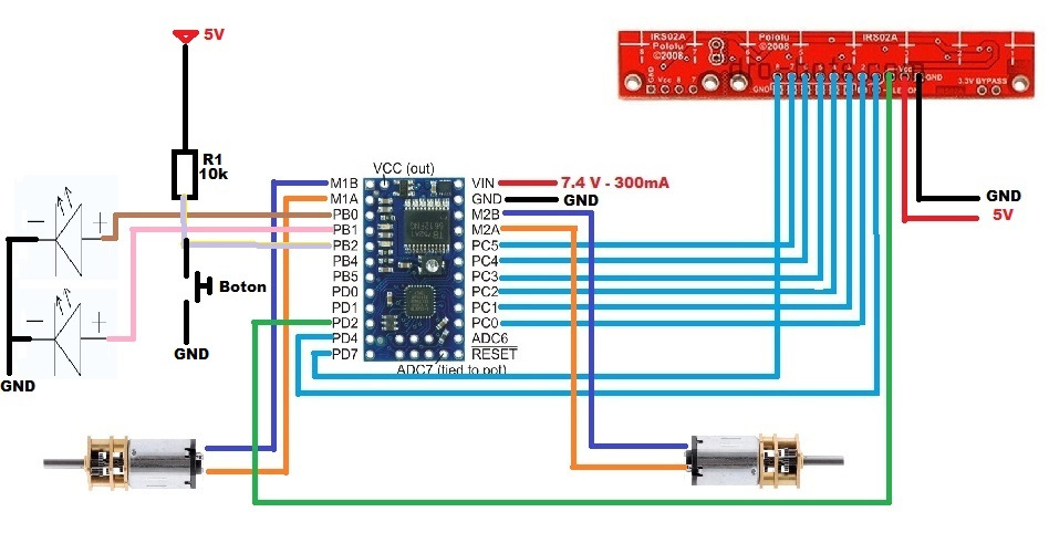
Microcontroller: Baby Orangutan 328p
Motors: Pololu 10: 1
Sensors: QTR-8RC
Code:
#include <OrangutanDigital.h>
#include <QTRSensors.h>
#include <OrangutanMotors.h>
//------------------------------------------------------------------------------------//
//Sensores de Linea PD
#define NUM_SENSORS 6 // Numero de sensores que usa
#define NUM_SAMPLES_PER_SENSOR 5 // Muestras por sensor
#define EMITTER_PIN 2 // emitter is controlled by digital pin 2
// sensors 0 through 5 are connected to analog inputs 0 through 5, respectively
QTRSensorsRC qtrrc((unsigned char[]) {14, 15, 16, 17, 18, 19},
 NUM_SENSORS, NUM_SAMPLES_PER_SENSOR, EMITTER_PIN);
unsigned int sensorValues[NUM_SENSORS];
OrangutanMotors motors;
//--------------------------------------------------------------------------------------//
//Velocidad Maxima Robot//--------------------------//----------------------------------//
const int maximum = 80;
//--------------------------------------------------------------------------------------//
//VALORES PD//----------//VALORES PD//--------------------------------------------------//
int VProporcional = 1.45;
int VDerivativo = 16;
//--------------------------------------------------------------------------------------//
//Velocidad de Calibracion
int velcalibrate = 20;
//--------------------------------------------------------------------------------------//
void setup()
{
 int inPin = 10;
 int val = 0;
 pinMode(9, OUTPUT);
 pinMode(8, OUTPUT);
 pinMode(inPin,INPUT);

 val = digitalRead(inPin);
 while (val == HIGH)
 {
 digitalWrite(9, HIGH);
 digitalWrite(8, HIGH);
 val = digitalRead(inPin);
 };
 if (val == LOW)
 {
 digitalWrite(9, LOW);
 digitalWrite(8, LOW);
};
 motors.setSpeeds(0,0);// Motores detenidos


//-------------Instrucciones para Empezar a hacer la Calibracion de Sensores--------------------------------------//

 delay(1500);
 digitalWrite(9, HIGH);
 digitalWrite(8, HIGH);// Enciende el leds para indicar que se esta calibrando.
 for (int counter=0; counter<21; counter++)
 {
 if (counter < 6 || counter >= 15)
 OrangutanMotors::setSpeeds(-velcalibrate, velcalibrate);
 else
 OrangutanMotors::setSpeeds(velcalibrate, -velcalibrate);
 qtrrc.calibrate();
 delay(20);
 }

 digitalWrite(9, LOW); // Apaga el led para indicar que se termino la calibracion.
 digitalWrite(8, LOW);

 OrangutanMotors::setSpeeds(0, 0);

 delay(200);
 digitalWrite(9, HIGH);
 digitalWrite(8, HIGH);
 delay(200);
 digitalWrite(9, LOW); // Parpadeo para indicar que el robot esta listo.
 digitalWrite(8, LOW);
 delay(200); // Parpadeo para indicar que el robot esta listo.
 digitalWrite(9, HIGH);
 digitalWrite(8, HIGH); // Parpadeo para indicar que el robot esta listo.
 delay(200);
 digitalWrite(9, LOW); // Parpadeo para indicar que el robot esta listo.
 digitalWrite(8, LOW);
 delay(200);
 //---------------------------Fin Calibracion de Sensores----------------------------------------------------//
pinMode(inPin,INPUT);

 val = digitalRead(inPin);
 while (val == HIGH)
 {
 digitalWrite(9, HIGH);
 digitalWrite(8, HIGH);
 val = digitalRead(inPin);
 };
 if (val == LOW)
 {
 digitalWrite(9, LOW);
 digitalWrite(8, LOW);
 delay(1000); // Retardo X segundos antes de Empezar a andar
};
}
unsigned int last_proportional = 0;
long integral = 0;
void loop()
{

 unsigned int position = qtrrc.readLine(sensorValues); // leemos posicion de la linea en la variable position

 // Referencia donde seguira la linea, mitad sensores.
 int proportional = (int)position - 2500;
 // Calculos PD
 int derivative = proportional - last_proportional;
 integral += proportional;
 last_proportional = proportional;

 int power_difference = proportional/VProporcional + integral*0 + derivative*VDerivativo;

 if (power_difference > maximum)
 power_difference = maximum;
 if (power_difference < -maximum)
 power_difference = -maximum;

 if (power_difference < 0)
 OrangutanMotors::setSpeeds(maximum, maximum + power_difference);
 else
 OrangutanMotors::setSpeeds(maximum - power_difference,maximum);
};