Always good to have the backup, i will buy the combo.
Purhaps i will still send my old baby0 in if you will allow it, which i have made an email RMA request, I would be interested in knowing the final verdict on what happened.
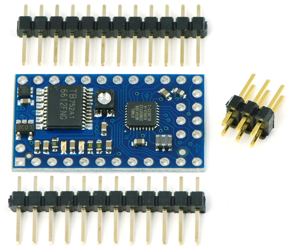
Do you have extra pins as shown in the photo, or within the order can you include extra pin,
I make + - connector out of them.
Oh also: in the AVR studio, Does the Baby168 and 328 use the same type of robot/link library ATmega168?
You can still send us your Baby Orangutan; I sent you an email with an RMA number and return instructions. Code written for the Baby Orangutan B-168 will run on the Baby Orangutan B-328 with little or no changes, but you will need to compile them using the correct settings. Specifically, you need to make sure the device is ATmega328P under Project -> Configuration Options, and you need to link in the libpololu_atmega328p.a version of the Pololu AVR library. You should also change the device to ATmega328P in the AVRISP dialog box.
You can post here if you have any problems getting it to work, but I don’t expect you to have any problems.
ok thx for all the help, i have turned a new leaf, i will never use 3volt ever again.
ANOTHER PROBLEM WITH MY OTHER BABYO:
I am having yet another connection problem with my #2 baby0168. The red light on the older programmer
is blinking which i believe indicates that the BabyO is getting no power or voltage drop maybe, and the
green light on the old programmer is solid green which means a good connection with the PC.
I am sure I am using at least 6volts to power the babyO ( i tested with a multi-tester ) , yet the red light continues to blink on the old programmer. I also tested continuity on the 6 pin connector on the baby0, all connections seem solid. I am stumped, at a loss. Could a loss of milliamps from the battery be causing this?
I don’t know
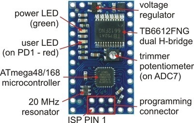
The blinking red light means that the programmer isn’t detecting any target voltage. What voltage do you measure with your multimeter on pin 2 of the Baby Orangutan’s programming header? It’s the pin directly across above pin 1 in the picture below:
Make sure you use the multimeter to measure voltage on the header pin in case there’s a problem with the connection between your header pin and the board. Also, you should make sure that you’re working with a freshly charged battery.
When you tested for continuity, what were your continuity test points for each pin?
Just to verify, so to test the voltage the test points would be pin1 and pin2 on the header , while powered up from a fully charged battery?
For continuity the test points were solder on the short side of the header to the same pin on the long side,
but i believe this was inconclusive and not accurate.
No, the important value is the voltage on pin 2 relative to ground, so you want to touch one probe to the long side of the pin 2 header pin and the other side to ground somewhere on your board.
You are correct, this test doesn’t really tell you anything. All you’ve demonstrated is that there is continuity through a single metal header pin. What you need to test for is continuity between the header pins and the board, since this is where the problem will be if your solder job is bad. I suspect that pin 2 is not well soldered to the board, which is why your programmer isn’t seeing a target voltage. Can you post a close-up picture of your programming header solder joints?
I believe the 6th pin on the header is the far upper right pin? If this is wrong, please let me know.
Yes i know its really a bad job, I will do it over with a heat sink Soldering torche, and try the concave method, and heat the part not the solder directly, thank you for that.
Yes, it’s the upper-right pin in the picture I posted earlier, in the opposite corner from pin 1. If everything looks normal, can you also try measuring the voltage between pins 1 and 6 on the programmer (probing the solder joints beneath the ISP header on the programmer) with the programmer plugged into the Baby Orangutan and the Baby Orangutan powered?
With the programmer plugged into the header and powered on, and babyO powered on pin 1 and 6 - 0.00 volts, when i reversed positive test and negative test leads it came up .4 something volts.
Oops, I meant to ask you to measure between pins 2 and 6 on the programmer, but I don’t think that is necessary since you should have measured 5V between 2 and 6 on the Baby Orangutan (which tells me the problem is on the Baby Orangutan and has nothing to do with the programmer). Pin 6 is supposed to be ground, and you measured 4.9V between 2 and ground on the board, so that indicates to me that there isn’t a good connection between pin 6 and ground. Can you do a continuity test from pin 6 to ground? If you don’t get good continuity, you should try touching up the solder on that pin.
Continuity between ground and 6 is nothing.
Continuity remains nothing even after redoing the solder joint.
I may have burned out the circuit board where it meets pin 6.
All other connections show continuity.
The baby0 is probably cooked, i must take more care in the future.
But thank you for all your help
Well, you know where the problem is now, so you might be able to find it and fix it. For example, you could potentially route a wire from ground to pin 6 to restore the connection. Also, I forgot to comment on this, but in your pictures it really looks like you have a solder bridge between one of your motor outputs and ground. If you ever try to use the motor driver you will create a short between VIN and ground and could damage things.
But yes, I recommend you get a better soldering iron (or a new tip) and try to take better care when soldering. Heat the pad and then apply the solder, and use just enough to make a nice, concave fillet. You can always practice a bit if you have any broken electronics lying around.
Oh thats seems like an easy fix on the ground and pin 6.
And i’m heading to the store to get solder, a finer tip, and magnifier too.
thx
culser.com/project/baby0.html
On the solder bridge do you mean Motor1? - Between the M1 pos & neg flats on photo 2? yes i see some sort of strand of solder
going between them. A little touch up there should do the trick.
No, I meant between M2 and GND on the top right side of that first picture, but I think maybe you just have a lot of wires connected to that ground and I’m not judging the depth correctly in that picture. In another picture I think I can see those wires passing above the M2 pad. Just make sure those wires and that solder isn’t touching the M2 pad beneath them.
Also, I’m going to have limited internet access until Monday, so I might not be able to reply to this thread in a timely manner for the next five days. If you have any more problems getting things working, hopefully someone else can jump in and help you out (but I’ll try to log in and check for posts when I can).
When I changed from the ATmega168 to the ATmega328p Ben gave me the folowing advice to make the software universal for both platforms. This allows you to maintain one code but does not solve the reference in projects and programmer dialogue.
There are a few ways to make your code work for both the B-168 and and
B-328:
Write and include a header file that has definitions like:
Use generic pin names that are automatically included in your code when you include <avr/io.h>. For example, you can use PORTB0, PORTD1, etc for both your ATmega168 and ATmega328P code. The generic pin names are located in the file: