I have a system consists of an ESC, mini maestro servo controller and a brushed dc motor. I am successfully driving my motor over servo controller. However I need to calculate RPM value of a.m. motor in order to create more realistic drive mechanism. Is there any way of doing it. Can I connect one of RC RPM sensors directly to mini maestro controller. If not can you suggest me any type of product which can help me to calculate RPM value. Please note that my motor consumes more than 12A and it is not possible for me to use motorcontroller with feedback. Is there any possibility that I can use any type of encoders to calculate RPM?
Do you have some documentation on your RC RPM sensors? What kind of interface do they have?
Do you know the stall current and no-load current of your motor? Note that our jrk 12v12 can handle a peak current of 30 A, so it would only be a problem if your motor draws more than 12 A continuously.
Actually I need some suggestions in order to instruct me to purchase hardware. If it is possible providing this functionality without purchasing a new motor controller, I prefer this sollution.
What are you sending the RPM values to? Generally speaking, you are going to need to have a microcontroller somewhere to use any kind of feedback speed control. I doubt the mini maestro can handle encoder input from it’s scripting language.
What do you mean by “realistic drive mechanism”? Basically, we need to know what you intend the feedback to be used for. If you just want to have linear control of the speed from the servo controller, then you are going to need something to go between the driver and servo controller.
You’re going to need to provide us with more details about what it is you are trying to do, and what you already have. What is controlling the servo controller?
I have brushed dc motor controller connected to ESC. ESC connected to one of the pins of mini maestro controller. From this far I can move motor forwards and backwards by sending pwm values to mini maestro. ie sending 1500 means motor stop, 1000-1500 means backwards, 1500-2000 means forwards. Mini maestro controller is connected to a mobile phone which has windows mobile os over bluetooth device. For this point everything works perfectly. Also I have a ultrasonic sonar sensor which provides me feedback about environment.
In some circumstancees I need to be sure whether motor is running or not. Also I need its actual speed. With this data my application decides what to do. Be sure that sending 1750 PWM to ESC controller doesn’t always produce constant linear speed, because of environmental conditions. In some circumstances more motor power required in order to have constant speed. If I can calculate speed of the robot somehow, I can adjust motor power by increasing or decreasing PWM value. I also I want to adjust the speed of the robot using the software by saying move forward 10 meters/sec.
It sounds like you pretty much need a microcontroller somewhere to read feedback sensors. I would suggest optical quadrature encoders on the wheels (exactly what kind depends on your robot’s hardware), and some small controller with external interrupts and a serial interface.
There are some quadrature decoder chips on the market, but good luck finding one available in your country and with a serial interface.
If you can’t use a microcontroller with feedback, well, there really are no other options without switching motor drivers (to something with an on-board microcontroller which measures feedback…). Of course, you still haven’t told us what ESC you are using, or what motors you’re using. How is the sonar sensor connected?
You can’t measure motor speed without some kind of feedback. To measure the feedback, you need a microcontroller/FPGA/CPLD/dedicated IC. This chip then needs some way of interfacing with your mobile device, which probably means serial.
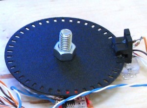
What kind of sensor you use is extremely dependent on your robot hardware. For example, these Vex Optical Shaft Encoders work very well if they aren’t too large for your robot, or Pololu product 1217 could work with a custom encoder disk, which can be designed and printed from a generator like this, or like this installable one. You also might want to take a look at this tutorial from SoR.
To read it, you will need a microcontroller. If you are new to microcontrollers, I suggest starting with an Arduino. If your mobile phone is reading the Maestro as a virtual serial port over USB, then you shouldn’t have any trouble using an Arduino with the same interface (different drivers though). I would specifically suggest the Arduino Nano, which unfortunately Pololu doesn’t carry. An Uno will work fine, it’s just significantly larger. Here is a list of Arduino distributors, perhaps one in your country carries Nanos. You can get them cheap from Ebay, but there is no quality guarantee. I did get one from there, and it worked, but YMMV. You would also need to find an option that ships to you.
Here is a tutorial page for reading encoders with an Arduino.
I will try Arduino + Pololu Encoder setup. I didn’t know that I can use pololu encoder with custom encoder disks, I read the specs, resolution of pololu encoder fits my needs, and custom disk will perform best in my configuration. This is good!
Is it possible to use mini maestro to read input from encoder, do I need microcontroller in any case? If I add arduino to project do I still need mini maestro to control my servos? (I checked the documentation of arduino and some of the pins can be used as PWM outputs). If I need mini maestro anycase, I am using sparkfun bluetooth module to connect mini maestro card, how can I control both controllers with single bluetooth device. Can I connect them together using daisy chain method? (sorry for these newby questions, I have no experience with microcontroller cards before. Also whole functionalities can be programmable in arduino it is cool and exciting)
The Maestro scripting is really meant for controlling servos and reading simple inputs. It could read encoder inputs, but it wouldn’t be able to do anything with them, and it probably can’t read them nearly fast enough for your application.
You can control servos with an Arduino. However, it wouldn’t be able able to control more than a couple without missing encoder inputs.
Daisy chaining Serial is not beginner friendly. It could be done, but it would be difficult. If you only have 1-4 servos, it will be far easier to use only an Arduino to control the servos, read from encoders and read the sonar sensor. The Arduino can connected to the Bluetooth module, but depending on whether it’s a 3.3V or 5V device, you may need level shifting. Most Arduinos run at 5V.
Using an Arduino to control servos and ESC will mean either doing some wiring (soldering or breadboard), or purchasing a shield. I would suggest a shield which breaks out the I/Os to three pin headers (like a servo controller), and has separate power for the digital pins, so that you can connect servos directly. Though a little pricy, this shield by DRrobot will do the trick. The sonar sensor can be used in analog mode from the 5V powered analog pins.
One possible problem with standard Arduinos is that they do not work well off of 6V, which is standard for RC systems. 7.4V LiPo works fine. What are you using to power your Maestro currently?
Unfortunately, it will be difficult or impossible to use our encoder board (product #1217) with other wheels. The product name is Encoder for Pololu Wheel 42x19mm.
I don’t see any reason the Pololu encoder wouldn’t work with an encoder disk. All it is is two reflection sensors set near each other. You wouldn’t mount it the same. The PCB would be parallel to the wheel and encoder disk instead of perpendicular. The calibration pots make it even easier. The stripes of the encoder disk need to be wider than the sensor, and they will need to be quite close (~.125").
Either of the products you posted could work, but for quadrature encoding you would need two for each wheel. The “Optical RPM Sensor” could still be used with an encoder disk, but the magnetic sensor would require you mounts magnets on your wheels. There are cheaper options, but you don’t have to solder wires to these, which is an advantage.
You don’t have to use quadrature encoding, but without it, you can only sense speed, and not direction. Sometimes that is fine, but if your wheel reverses directions quickly, you can get a false reading which shows high speed. This method only requires one sensor per wheel.