I need to power a massive 1/4 scale servo that needs 5VDC and standard PWM control. I love the Maestros, have been using them for years.
I need to know if I can connect the Maestro and the servo to a single 5VDC (70 A) power supply.
If so, does this wiring diagram look OK?
It should generally be fine to power the Maestro and servo from the same supply. In that kind of setup, the Maestro and servo should share a common ground connection. I am not sure why you have the ground rail on the Maestro connected to the AC ground on your power supply (that should not be necessary, but it’s probably okay to do), but please note that all of the grounds on the Maestro are connected internally (i.e. the GND pin for the VIN power is also connected to the GND rail for servo power).
The other potential concern would be noise or voltage dips; since the Maestro’s minimum operating voltage is 5V, and you’re right at that minimum voltage, it might be possible for the servo to draw enough current from the supply to cause the voltage to dip enough to cause the Maestro to brown-out and reset.
To be clear the only grounds that need to be connected are the Maestro to the servo, correct? So I am absolutely clear here’s the last stupid question: the ground for the servo is the black lead, correct? That would mean that I would need to connect that to the ground on on the Maestro AND the -5V black terminal on the DC supply, right? Just checking.
Servos can have different coloring schemes for their wires, but they usually use either white,red, black or orange, red, brown with black and brown being the ground wires, respectively. If your servo uses a different color scheme (or if you just want to be extra careful), I recommend checking the manufacturer’s documentation.
The Maestro, the servo, and the power supply should all have a common ground. The “negative” terminal on your power is very likely a ground connection (and not actually some -5V rail), in which case, you can make your ground connection there. (The separate green ground terminal should correspond to the ground on the AC side, meaning you can leave it disconnected to have isolated outputs on your power supply or connect it to the black terminals to share a common ground between AC and DC.) You can double check this by measuring the voltage between the negative and positive terminals with a multimeter; if you see 5V across them, then it is a ground, but if you see 10V across them, it is a negative voltage source.
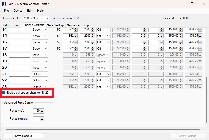
Quick Q: using a relay to trigger a sequence in a 24 channel Maestro. The manual says channel 18,19, and 20 can be used without having to install an external pull-up resistor. It says in channel settings to enable the internal pull-up resistor…but all I can see is the option to make that channel an “input”. Does that automatically enable the resistor or do I need to do something else?
Thanks!
After configuring them as inputs you will need to enable the “Enable pull-ups on channels 18-20” option, which is located at the bottom of the servo channel list:
It looks like your ENDIF command is commented out. For reference, in the Maestro scripting language an IF command must be “closed” by an ENDIF command (and if applicable, an ELSE command should be between them. For example:
trigger18 if # Sequence 0
  #code here will run if trigger18 returns true

else
  #code here will run if trigger18 returns false

endif
The incompetence is strong in me! So instead of buggin you I asked GROK A.I. to help. I fed it the whole Maestro PDF manual. It processed it and gave me this working script: