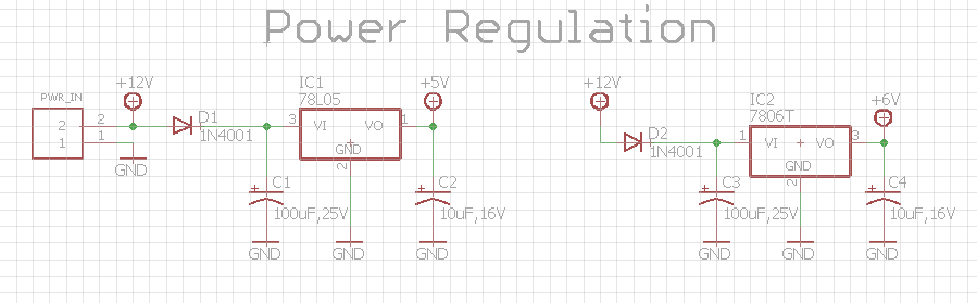
I’ve made a DC motor driver board that also runs 20 LEDs for a project I’m working on and after some prototyping I found that the approach I’m using for 5V voltage regulation might not be the best way as the IC gets very hot (it doesn’t help that I forgot to account for driving the LEDs with the 5V so I’d designed the board to use a 78L05 which can only handle 100mA; turns out the current draw is closer to 300mA). This is my schematic for the voltage regulation part (I’ve been doing it this way for years):
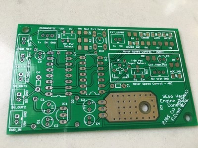
My initial worry was about the 6V voltage regulator for the motors so I created a heat sink pad on my PCB (it does indeed get warm/hot, around 110 deg F):
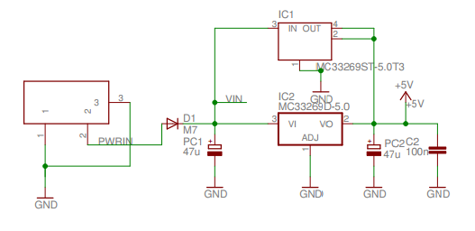
If I have 12V input and I need to drive 300-400mA of current at 5V, is there a better voltage regulation design that won’t require a huge heat sink on the PCB? For example, the Arduino Uno schematic (https://www.arduino.cc/en/uploads/Main/arduino-uno-schematic.pdf) shows this:
I’ve never seen this approach before, so if this is what I should do I would greatly appreciate any info on this.
I think that Jim was referring to the Arduino schematic. However, I am pretty sure that the two regulators that are shown in parallel in the schematic are not really used in parallel on the board. They are two different packages of the same regulator and the schematic probably has them both so both footprints are included on the board and either can be used on the final Arduino. A newer version of the Arduino Uno R3 schematic that can be found on the Uno’s official page shows only one 5V regulator.
As for the issue of your linear regulator getting hot, I would definitely expect any regulator handling triple the rated current to at the least get very hot, if not break. If you want to continue using linear regulators, your original schematic seems fine, but you should get a regulator that can handle enough current for your LEDs. Though, I would recommend using a switching regulator instead. Switching regulators are much more efficient (so they generally run cooler) and you could probably find a pre-made module that is almost as small as your current linear model. We have several 5V step-down voltage regulators that might work for you. In particular, you might consider our D24V5F5 regulator for powering your LEDs.
I think that Jim was referring to the Arduino schematic. However, I am pretty sure that the two regulators that are shown in parallel in the schematic are not really used in parallel on the board. They are two different packages of the same regulator and the schematic probably has them both so both footprints are included on the board and either can be used on the final Arduino. A newer version of the Arduino Uno R3 schematic that can be found on the Uno’s official page shows only one 5V regulator.
As for the issue of your linear regulator getting hot, I would definitely expect any regulator handling triple the rated current to at the least get very hot, if not break. If you want to continue using linear regulators, your original schematic seems fine, but you should get a regulator can handle enough current for your LEDs. Though, I would recommend using a switching regulator instead. Switching regulators are much more efficient (so they generally run cooler) and you could probably find a pre-made module that is almost as small as your current linear model. We have several 5V step-down voltage regulators that might work for you. In particular, you might consider our D24V5F5 regulator for powering your LEDs.
-Claire[/quote]
Thanks very much, Claire! I’ll check out the links for pre-made modules.