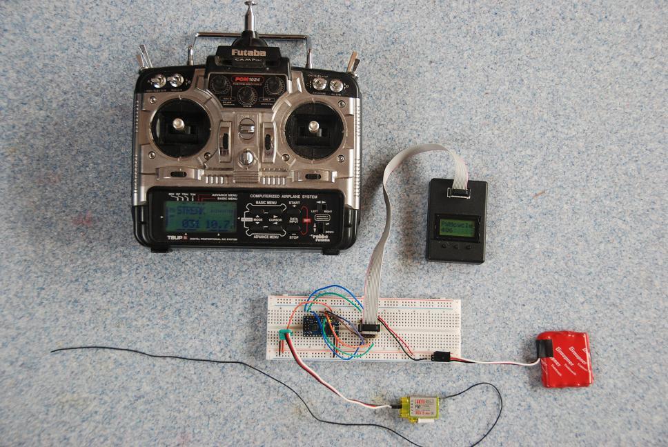
I found some bits an pieces and created this software to catch the pwm signal from a RC receiver with my ATmega168 baby-O. The result is a useful signal with a range from 0 to 1000 which allows me to remotely control a motor with PID software that runs on my baby-O (PID in other topic)
The LCD software comes from the LV168 to which the LCD_RW connection was moved to PB2 in order to free the PB0 for input capture.
#include <avr/io.h>
#include "device.h"						// pinout definitions for the Orangutan LV-168
#include <util/delay.h>					// F_CPU is defined in "device.h" above
#include <avr\interrupt.h>				// added for pwm capture
#include "lcd.h"						// provides routines for using the LCD

uint16_t rising, counts;				// define rising and counts

ISR(TIMER1_CAPT_vect)
{
	uint16_t t = ICR1;
	if (TCCR1B & (1<<ICES1))
	{
		TCCR1B &= ~(1<<ICES1);			// falling edge next
		rising = t;
    }
	else
	{
		TCCR1B |= (1<<ICES1); 			// rising edge next
		counts = (((t - rising)*10)/25);
		if ( counts <= 1000 ) { counts = 1000; }	// minimu value is 1 ms
		if ( counts >= 2000 ) { counts = 2000; } 	// maximum value is 2 ms
		counts = ( counts - 1000 );					// delivers o/oo
    }
}

void delay_ms( unsigned int time_ms )	// delay for time_ms milliseconds by looping
{
	unsigned int i;
	for ( i = 0; i < time_ms; i++ )
		_delay_ms( 1 );
}

int main()
{
	TCCR1B |= (1 << CS11); 				// Start timer at Fcpu/8
	TIFR1 = (1 << ICF1);   				// clear interrupt-flag
    TIMSK1 |= (1 << ICIE1);				// enable Timer1 input capture interrupt

	sei(); 								// Enable global interrupts

	lcd_init();							// this function must be called before any other LCD command

	while (1)
	{
	lcd_gotoxy(0, 0);					// go to the start of LCD line 1
	lcd_string("PWMcycle");
	lcd_gotoxy(0, 1);					// go to the start of LCD line 2
	lcd_int(counts);				// display pwm as an integer o/oo
	lcd_string("        ");				// overwrite any LCD character remnants
	delay_ms(100);
	}

	return 0;
}
Nice idea! I’ll have to dig out my old RC setup and play a bit.
One thing to watch out for is reading counts. The code in main could be interrupted by pulse interrupt and corrupt the reading. You could put a cli() and sei() around the read:
Very cool, thanks for sharing your code with us! By the way, have you tried out the Pololu AVR library yet? It represents our most up-to-date code for the Orangutan robot controllers (the code you are using in devices.h and LCD.h predates the library and has since been included in the library). It also contains code for reading arbitrary pulses on arbitrary pins using pin-change interrupts and timer 1. It’s not documented quite yet, but I made a post about using it here:
Using the timer capture is an elegant way to read the pulses from a single channel of your receiver, but it can’t really be extended well to simultaneously reading multiple channels. The following example program will be included with the next release of the library, which should hopefully be available by the end of this week or early next week:
#include <pololu/orangutan.h>

/*
 * pulsein1: for the 3pi robot, Orangutan LV 168, Orangutan SV-xx8, Orangutan SVP,
 *   or Orangutan X2
 *
 * This program uses the OrangutanPulseIn functions to control measure hobby servo
 * pulses connected to pin D0.  It also generates hobby servo pulses on pin D1,
 * so if you do not have a external pulse source (such as an RC receiver or a
 * servo controller), you can use a wire to connect D1 to D0 and see the PulseIn
 * library measure the pulses put out by D1 and display the high and low durations
 * on the LCD.
 *
 * https://www.pololu.com/docs/0J20
 * https://www.pololu.com
 * https://forum.pololu.com
 */

// This array of pins is used to initialize the PulseIn routines.  To measure
// pulses on multiple pins, add more elements to the array.  For example:
// const unsigned char pulseInPins[] = { IO_D0, IO_C0, IO_C1 };
const unsigned char pulseInPins[] = { IO_D0 };


int main()
{
	unsigned long time_ms = get_ms();
	unsigned int high_pulse_us = 1000;
	char upcounting = 1;

	set_digital_output(IO_D1, LOW);

	clear();  // clear LCD

	// using the parameter MAX_PULSE_26MS means we can only measure pulses
	// up to 26 ms long, but gives 0.4 us resolution.  This is a good setting
	// for hobby servo pulses, which are usually 50 Hz signals (20 ms period).
	// Other options are MAX_PULSE_3MS, _200MS, _800MS, and _3000MS.
	pulse_in_init(pulseInPins, 1, MAX_PULSE_26MS);

	while (1)  // main loop
	{
		pulse_in_update();  // this must be called at least once every 26 ms
							// when using MAX_PULSE_26MS

		struct PulseInputStruct pi = get_pulse_info(0);  // get pulse info for D0

		if (pi.curPulseWidth == MAX_PULSE)
		{
			// input line has been in the same state for longer than we can time
			// (e.g. it is held high or low)
			if (pi.inputState == HIGH)
			{
				lcd_goto_xy(0, 0);	// go to start of first LCD row
				print("D0: HIGH");
				lcd_goto_xy(0, 1);	// go to start of second LCD row
				print("        ");	// clear the row by overwriting with spaces
			}
			else
			{
				lcd_goto_xy(0, 0);	// go to start of first LCD row
				print("        ");	// clear the row by overwriting with spaces
				lcd_goto_xy(0, 1);	// go to start of second LCD row
				print("D0:  LOW");
			}
		}
		else if (pi.newPulse == HIGH_PULSE)
		{
			lcd_goto_xy(0, 0);		// go to start of first LCD row
			// print the length (in us) of the most recently received high pulse
			if (pi.lastHighPulse != MAX_PULSE)
				print_unsigned_long(pulse_to_microseconds(pi.lastHighPulse));
			print(" us    ");
			lcd_goto_xy(0, 1);		// go to start of second LCD row
			// print the length (in us) of the most recently received high pulse
			if (pi.lastLowPulse != MAX_PULSE)
				print_unsigned_long(pulse_to_microseconds(pi.lastLowPulse));
			print(" us    ");
		}

		// generate pulse output on pin D1
		if (get_ms() - time_ms >= 20)
		{
			time_ms = get_ms();
			set_digital_output(IO_D1, HIGH);
			delay_us(high_pulse_us);
			set_digital_output(IO_D1, LOW);

			if (upcounting)
				high_pulse_us += 10;
			else
				high_pulse_us -= 10;

			if (high_pulse_us > 2000)
			{
				high_pulse_us = 2000;
				upcounting = 0;
			}
			if (high_pulse_us < 1000)
			{
				high_pulse_us = 1000;
				upcounting = 1;
			}
		}

	}
}
Everything about this program should work with the current release of the library except for the function pulse_to_microseconds(), which is being included in the next release.
Putting the cli and sei around the reading is probably the proper way to do it.
Another remark to be made is that it only counts right if there is a maximum of 1 overflow between the rising and falling edge, if not the reading will be wrong. You could count the number of overflows and extend the reading.
The futaba signal is 1-2 ms
An overflow takes 1 / (20000000/8/65336) = 26 ms so it can only happen once per duty cycle
In my future application I have the following challenge to meet:
I want to use the pololu motor driver at a resolution of 1024 so I need Timer1 pwm
If I read the datasheet well the ICR is disabled when pwm is used, replacing ICR with TCNT1 should solve this
The motor needs to change direction when a HALL sensor is activated so I cannot start/stop the interrupts, maybe I have to store the previous value and if it is not the same ignore the Rx input.
I have little experience in interrupts, bright ideas are welcome.