I am wondering if I have a bad board or just missing something.
I received my Baby O and solder it up, plugged it into a breadboard, hooked up power and the programmer with AVR Studio 6 and the AVR Programmer module and got the red_led to flash no problem.
I moved on to the motor example and I get no voltage out of motor 1 but motor 2 is working fine.
The code is from the sample that you provide that uses set_motors and uses the same value for motor1 and motor2.
I can’t see any problems with the pin connections or solder.
Can you make any suggestions?
I will try controlling the individual motors with their individual commands tonight but that would only say that the example is bad or the code provided has a problem. The led flashes per the potentiometer and if I change the pot the motor speeds up, slows down and reverses directions on Motor 2 only. Again motor1 reads 0vdc regardless of the pot position.
I am sorry you are having trouble with your Baby Orangutan.
We have two motor examples that match your description. Could you please tell me the full path of the folder where you found this example code, and paste the code here, so I can know exactly what code you are running?
How are you measuring the voltage of motor1? Do you have an actual motor connected to the motor output pins? If you have two motors connected and it is easy to swap them, please try that and tell us what happens.
Thanks for the quick reply.
I will have to get you the code later as I don’t have the path right now.
I can tell you that it is the motor1 example that you provide without the lcd display code.
Essentially it reads the potentiometer and sets the motorspeed to the normalized value of it something like /2-256.
It then uses set_motors( motorSpeed, motorSpeed ) to set both motors to the value related to the pot.
It also flashes the red_led based on the same value.
I used AVR Studio 6.0 but had to open the example as a project since the templates didn’t show up in Studio 6. If you could advise on that too it would be good.
The path was something like c:\lib-pololu something \ examples\ motor1\ something.proj6 again this is only a sudo path as I am not on that machine and going from first time use-memory.
As for testing (m1A & m1b) and (m2a & m2b) I have a motor that I plugged into M1 first that’s when I got no movement. I reprogrammed the AVR thinking I had forgot something and retried it (I’m new to AVR, more of a Microchip guy), that’s when I got out the DVM and measured the voltage of the pins and got 0vdc. Then I realized that your example was turning on both motors simultaneously and thought to check out M2 and it read 3.54 Volts DC. So I hooked up the motor that I had used on M1 and it fired right up. I then played with the pot and the motor performed as it should have as well as the red_led. I then unplugged the motor from M2 and put it back on M1 obviously turning off the Baby O while making connections and nothing even when adjusting the pot. DVM reported 0VDC always on M1 even with pot at its limits.
Here is the exact path to the example file that I used.
C:\libpololu-avr\examples\atmega328p\motors1
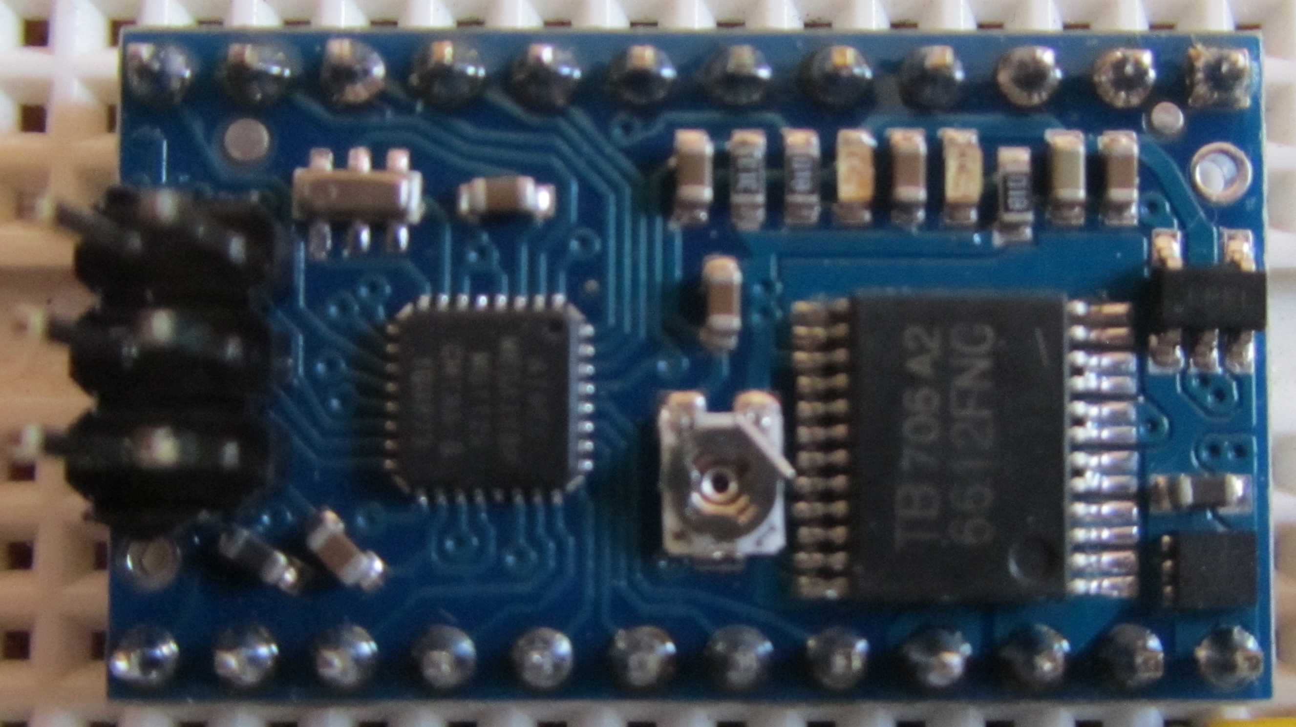
I have attached a clear jpg of my Baby O.
I suspect from looking at the photo that their seems to be an alignment issue possibly with the motor controller chip.
The pins at the output of the board look good to me.
Please let me know what you think.
Exact code from AVR Studio 6.0 that compiled and loaded successfully!
#include <pololu/orangutan.h>

/*
 * motors1: for the Orangutan LV, SV, SVP, X2, Baby-O and 3pi robot.
 *
 * This example uses the OrangutanMotors functions to drive
 * motors in response to the position of user trimmer potentiometer
 * and blinks the red user LED at a rate determined by the trimmer
 * potentiometer position.  It uses the OrangutanAnalog library to measure
 * the trimpot position, and it uses the OrangutanLEDs library to provide
 * limited feedback with the red user LED.
 *
 * [pololu.com/docs/0J20](https://www.pololu.com/docs/0J20)
 * [pololu.com](https://www.pololu.com)
 * [forum.pololu.com](https://forum.pololu.com)
 */

int main()
{
  while(1)
  {
    // note that the following line could also be accomplished with:
    // int pot = analogRead(7);
    int pot = read_trimpot();    // determine the trimpot position
    int motorSpeed = pot/2-256;  // turn pot reading into number between -256 and 255
	if(motorSpeed == -256)
		motorSpeed = -255; // 256 is out of range
    set_motors(motorSpeed, motorSpeed);

    int ledDelay = motorSpeed;
	if(ledDelay < 0)
	  ledDelay = -ledDelay;  // make the delay a non-negative number
	ledDelay = 256-ledDelay; // the delay should be short when the speed is high

    red_led(1);       // turn red LED on
    delay_ms(ledDelay);

    red_led(0);       // turn red LED off
	delay_ms(ledDelay);
  }
}
Thank you for the additional information and the photo.
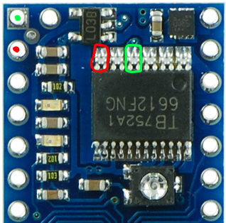
Each of the two motor output pins M1A and M1B are connected to pins of the TB6612FNG motor driver. In the diagram below, a red dot indicates M1A and the two pins circled in red are the driver pins it is supposed to be connected to. Similarly, a green dot indicated M1B and the two driver pins circled in green are the pins it is supposed to be connected to.
Could you please measure the voltage difference between the two circled pairs of TB6612FNG pins while the example code is running and the pot is in a position that causes motor 2 to turn? Be careful not to short out anything.
It would also be good to check for continuity between the circled pins and the other parts of your system that you would expect them to be connected to.
I ohm’d out from the motor controller to the pins as you show with red and green and they read shorts as they should and they are not shorted to each other all good. So the problem isn’t there.
So I had another Baby O. still in the wrapper but from the same batch probably as they were purchased together. I just built it up (very carefully!) and programmed it with the same example code. Low and behold it has the same issue. I was really hoping it was just one board.
So now we’re either dealing with a bad batch or code???
I will attempt rewriting the code to use the single-motor commands and see if that makes a difference.
I am using Studio 6 on a Windows 7 64-bit laptop, I installed the Studio first then the complete driver package as per the instructions on your site.
Please try disconnecting all motors and just measuring the voltage difference between the two pairs of driver pins. Do you get the results you would expect when you turn the pot?
I am not sure why one of the channels works while the other doesn’t, but I suspect that problem is with your power supply. As it says in the announcement at the top of this forum, 9V batteries are not generally strong enough to drive motors. If the Baby Orangutan behaves as expected when the motors are disconnected, then the problem is almost certainly with your power supply.
If the motor draws too much current from your battery, the battery voltage will drop and cause the Baby Orangutan to reset. You can use the LED on the Baby Orangutan to debug this further: if you program it to blink a few times on startup before driving the motor then you can tell whenever the Baby Orangutan is getting reset.
Please read my previous posts, I appreciate the help but I feel like we are going in baby steps.
Originally I checked the voltages across the the motor pins with a dvm without a motor attached and they are not as expected but remain that motor2 is functional and motor1 is not.
For the record I only have one motor and when I was connecting it it was only connected to 1 port at a time.
Always motor2 works with nothing on motor1, then turn off Baby O. unplug motor from motor2 and plug it into motor1 turn on Baby O. and nothing.
No motor connected, turn on Baby O. measure motor1 and it is 0 volts, measure motor2 3.5 volts.
I’m pretty sure I related this in earlier posts.
I have 2 Baby O’s that do the same thing. I can check the power but that doesn’t make sense that one would work while the other wasn’t especially with no load (motor connected).
I understand that problems like this can be frustrating, but please know that we are seriously trying to help figure out what is going on, and I hope you can appreciate the difficulty in trying to remotely debug subtle, complex issues. We test each board before it ships and we have no similar reports of problems with Baby Orangutans, so this is almost certainly a problem with how you are using the boards.
Your power source is simply not appropriate for this kind of application, so it doesn’t make sense to continue troubleshooting until that is addressed. Power problems can manifest in all kinds of counterintuitive ways in systems like these, including the behavior you are describing. Since I don’t see anything else obviously wrong with your setup, power problems are my top suspect. If it’s not power, the next most likely culprit is that somehow you aren’t making the connections you think you are, and a picture of your setup showing your actual connections might help us spot a problem.
Just for the sake of not going insane, try repositioning the BabyO on the breadboard. Breadboards have been know to go bad in bizarre ways sometimes. It could be causing a short on the motors pins.
I already thought of the and have moved the Baby O. on the breadboard to another location and no joy.
Plus I measured the voltage right at the pins of the Baby O.
I was able to reproduce your problem here. There seems to be some problem with the library (or perhaps an incompatibility with Atmel Studio) that is causing the problem with motor 1. I will try to figure out why and make a new release of the library that fixes it. In the mean time, please try the example code below:
/* babyo_full_speed - an application for the Pololu Baby Orangutan B-328
 *
 * Blinks the red LED three times, then turns on the red LED and drives both
 * motors full speed forward.  This is useful for troubleshooting the motor
 * drivers.
 *
 * This application uses the Pololu AVR C/C++ Library.  For help, see:
 * -User's guide: https://www.pololu.com/docs/0J20
 * -Command reference: https://www.pololu.com/docs/0J18
 *
 * Created: 2012-07-09 1:40:12 PM
 *  Author: david
 */

#include <pololu/orangutan.h>

void setM1Speed(int speed)
{
	unsigned char reverse = 0;

	if (speed < 0)
	{
		speed = -speed;	// make speed a positive quantity
		reverse = 1;	// preserve the direction
	}
	if (speed > 0xFF){ speed = 0xFF; }

	if (reverse)
	{
		OCR0B = 0;		// hold one driver input high
		OCR0A = speed;	// pwm the other input
	}
	else	// forward
	{
		OCR0B = speed;	// pwm one driver input
		OCR0A = 0;		// hold the other driver input high
	}
}

void setM2Speed(int speed)
{
	unsigned char reverse = 0;

	if (speed < 0)
	{
		speed = -speed;	// make speed a positive quantity
		reverse = 1;	// preserve the direction
	}
	if (speed > 0xFF){ speed = 0xFF; }

	if (reverse)
	{
		OCR2B = 0;		// hold one driver input high
		OCR2A = speed;	// pwm the other input
	}
	else	// forward
	{
		OCR2B = speed;	// pwm one driver input
		OCR2A = 0;		// hold the other driver input high
	}
}

int main()
{
	red_led(1);  delay_ms(200);
	red_led(0);  delay_ms(200);
	red_led(1);  delay_ms(200);
	red_led(0);  delay_ms(200);
	red_led(1);  delay_ms(200);
	red_led(0);  delay_ms(200);
	red_led(1);

	set_motors(0, 0); // only need to do this once at the beginning

	setM1Speed(200);
	setM2Speed(200);

	while(1)
	{
		// nothing
	}
}
The setM1Speed and setM2Speed functions that I had to write are basically just copied from OrangutanMotors.cpp in the library.
David - Thank You so much for validating this, I was beginning to think I was going insane.
Today I put leads on a 500ma - 9VDC power pack and as I suspected it wasn’t power, now we know it’s in the library at least. I need to really acquaint myself with the library source code and start to figure these avr critters for myself.
Thanks for your efforts! I am surprised no one else has reported this problem before.
I am also curious how to create my own project and include the pololu libraries but the functions don’t work when I do that. All the advice I’ve seen so far is to use the examples of templates, I would really like to know how to create a new project and be able to call pololu functions by including the .h files. The compiler never finds the functions even though the #include <pololu/orangutan.h> is correct.
Please see the “Using the Pololu AVR Library for your own projects” section of the Pololu AVR C/C++ Library user’s guide. Also, you can open one of our templates and see how we configured it by going to Project -> [Project Name] Properties… -> Toolchain.
I believe your problem comes from bug 13697 of GNU binutils 2.22, which is one of the open source components of the Atmel AVR Toolchain for Windows which powers Atmel Studio 6.
For now, I recommend working around this problem by adding the following code to your program:
By adding a variable that is not initialized to zero, this code ensures that the .data section will be non-empty, so it will not be garbage collected by the linker. After you add this bit of code, you should be able to use the rest of the Pololu library in the standard way and you can get rid of the previous workaround I gave you.
We will release a new version of the library soon that addresses this.
You have:
“set_motors(0, 0); // only need to do this once at the beginning”
This is calling the pololu library function, I’m assuming that you did this just to set the initial parameters of the AVR controller, output pins, pwm etc???