I am just moving from Arduino and a TB6612 to a Baby O. I soldered my headers on and downloaded and installed the AVR studio. Tried to run the first tutorial to get the LED on the Baby O to blink. No joy.
The green light is lit on the AVR. The yellow led on the AVR is blinking. The green light is on the Baby O. I feeding it +5V (actual measure on the board +5.34V). I can connect to the AVR. When I try to read the signature, it errors out on “entering programming mode” and returns with and “ISP Mode Error” window. I now have steady red led on the AVR, a blinking yellow and a solid green.
The Pololu configuration utility says for the error from last programming “The SPI command for entering programming mode was sent, but the expected response from the target was not received. Make sure that the ISP frequency setting is less than 1/4th of the target’s clock frequency.”
I did have some difficulty soldering - had to buy a new iron right in the middle of the putting the headers in. But this did not affect the USB programmer header and the LED is lit showing that the power and ground are connected.
Any help I can get would be greatly appreciated. Thanks.
I’m sorry you are having trouble with the Pololu USB AVR Programmer and your Baby Orangutan.
Please make sure that you soldered the programming header in correctly and that the arrow on the 6-pin programming connector lines up with the arrow on the Baby Orangutan. If that doesn’t help, could you post a high resolution picture showing your solder joints on the 6-pin header?
For anyone following this thread who might be confused: the Baby Orangutan only has a green power LED and a red user LED. When ggengel talks about “the AVR” I’m pretty sure he’s talking about the Pololu USB AVR Programmer, which has a green USB led, a yellow status LED, and a red error LED.
Thanks for replying. Yes, you understood my overly terse use of the AVR to mean the USB AVR programmer. I will use the longer notation in the future.
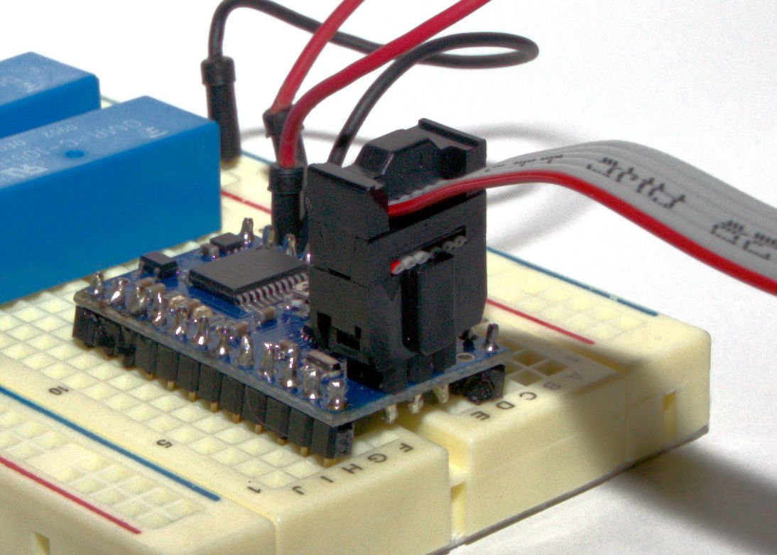
I will post high resolution photos later tonight when I get home from work. I am assuming you want the pictures from the bottom of the pins to check solder fillets - so I unless I hear otherwise, I will post a picture of that and a picture of the USB AVR programmer’s cable attached to the Baby Orangutan 328P so you can that check pin 1 is properly aligned.
Question - Do I post the picture directly in this or do I post it to Picasa (or equivalent) and the paste a link?
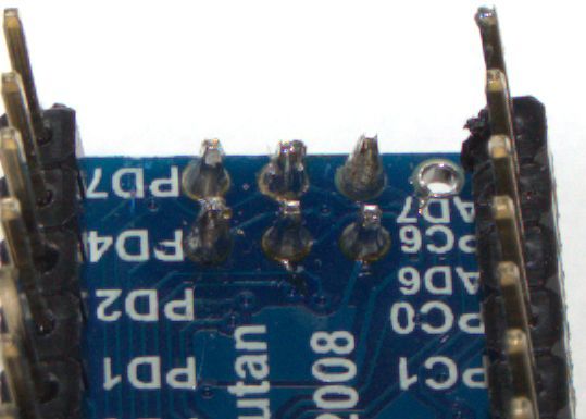
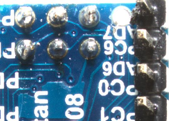
I am attaching pictures of the solder fillets on the bottom of USB AVR programmer attached to the Baby Orangutan. I hope the picture is good enough to show what you are looking for. Let me know if need something else.
I am also attaching a picture of the solder fillets on the bottom of the USB header on the Baby Orangutan. Again, let me know if you need something different.
Your soldering looks OK and you are plugging the programmer in the right way.
The error message you are getting (“expected response from the target was not received”) indicates that the programmer is detecting the VCC of your Baby Orangutan, so your GND and VCC connections are probably ok.
It would be worthwhile to check all six connections with a multimeter. Do you have one available? If so, I can give you further instructions on what to check.
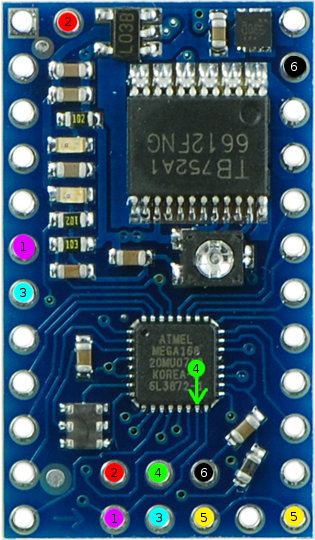
Here’s a diagram showing what to test. For each ISP pin, I labeled it with a color and a number, and a I labeled a corresponding point on the board that it should be electrically connected to. With the board powered off and disconnected from everything, please put your multimeter in continuity testing mode (resistance) and verify that there are connections between each ISP pin and its corresponding point on the board.
For pin 4, there is no easy access point so you’ll have to actually probe a pin on the microcontroller. This will be a better test anyway, because it will detect if there is a soldering problem between the microcontroller and the board. You might want to do that extra test for all the other 5 pins if you don’t find any continuity errors.
I just probed out all the pins - all show 0.1 ohms. I also probed them out through the jumper between Baby Orangutan and the AVR programmer for good measure. They all checked out.
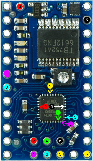
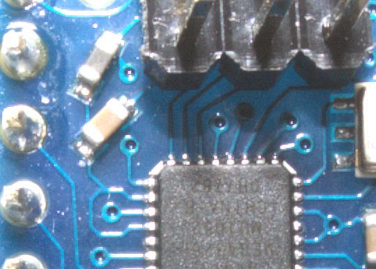
It’s possible that there is a soldering problem between the chip and the board or one of traces on the board between the AVR’s pins and the ISP header have been damaged. I added labels to the picture for the pins on the AVR. Could you test for continuity between the ISP pins and the corresponding pins on the AVR? You already tested pin 4, so there are just 5 things to test. Sorry for the inconvenience! Hopefully we can figure out what’s wrong and fix it.
Can you look at that pin carefully and see if there is a good solder connection between the pin and the board?
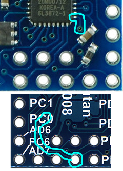
Also, in the image below I have outlined the trace going from ISP pin 3 to the chip. It runs along the bottom side of the Baby Orangutan for most of the way, and then goes into a via (hole) to get the top of the board. Could you look at that trace and the via and see if they look OK?
Visual inspection reveals the via is off center, but the via is completely captured by the pad. The traces on both sides look to be intact - unless there is defect under the nomenclature. This kind of indicates a void in the via barrel as the most likely culprit. Here are the pictures of the traces.
For anyone following this thread, ggengel has contacted us directly and we have sent him another unit to see if he has the problem with that one. --David