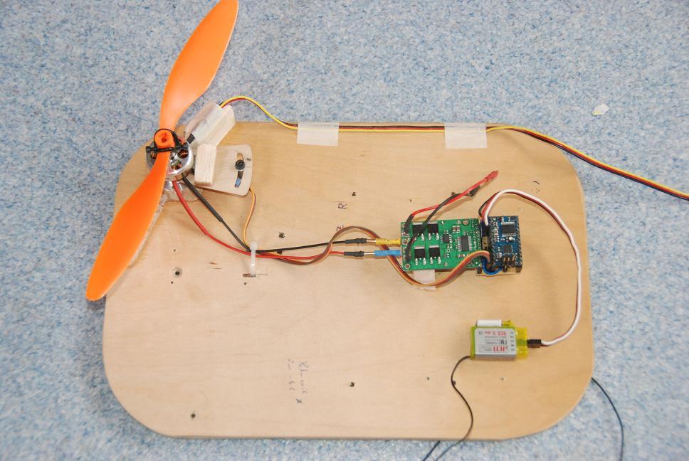
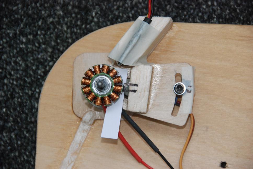
I wondered whether a stepper motor could spin really fast. For this purpose I have built my own 12 teeth stator with North and South poles alternating. The cage has 12 magnets too, also North and South alternating. The motor has to be flipped over to start.
For safety reasons I use the Overflow interrupt of Timer0 to cut the power, in this manner there is no power to the outputs when the motor is “stalled” The motor interrupt counts the number of turns and resets the overflow timer, it never fires until the motor is stalled.
For controlling the pwm I use Timer2 at a rate of 10 kHz, the M2A output is used towards the PWMH input, a hardware jumper allows a duplicate signal to PWML.
The Rx input (counts) was captured through Timer1 input capture as explained in an earlier post.
The HALL sensor gets the power directly from the processor on port PD7 and PD4, PD2 (INT0) is used for the external interrupt. I made a counter that gives the DIR change a little slack to reduce the induction from the coils.
The motor spins really fast, with a 11000 NO LOAD rpm the DIR changes at 2200Hz, at 50 Watts it spins a prop at 6000 rpm which is comparable to a classic motor. A short demo is available at Youtube, search for Pololu POC
ISR(TIMER0_OVF_vect) // STALL PROTECT
{
	if ( turns <= 3) // Motor is NOT running, keeps motor OFF before started by hand
	{ OCR2A = 0; } // set duty cycles for brake
	turns = 0;
}

ISR(INT0_vect) // HALL INTERRUPT
{
	turns = ( turns + 1 ); // count number of turns running
	if ( turns >= 3)
	{
	OCR2A = 0; TCNT0 = 0; // give DIR change some slack, reset overflow timer
		if ( (PIND & (1 << DDD2)) == 0 ) // if HALL is LOW
		{ PORTB &= ~(1 << DDB4); } // drive DIR pin PB4 LOW
		else
		{ PORTB |=  (1 << DDB4); } // drive DIR pin PB4 HIGH
	OCR2A = (counts); // put the power back on
	}
	if ( turns >= 100 ) { turns = 10; } // prevents overflow
}
Baby-O muscle power pictures.pdf (514 KB)