I bought one of the Pololu AVR Programmers V2.1 from a UK distributor. Great little programmer.
I was using it with Arduino Nano’s (Chinese clones) to upgrade or remove the bootloader. I have 2 different lots of these. The first lot worked right off the bat, and the second lot, which is already installed in circuits and hard to remove, won’t work. (I initially suspected in circuit shorts etc, but that wasn’t it…see below). I always get: “avrdude: initialization failed, rc=-1”
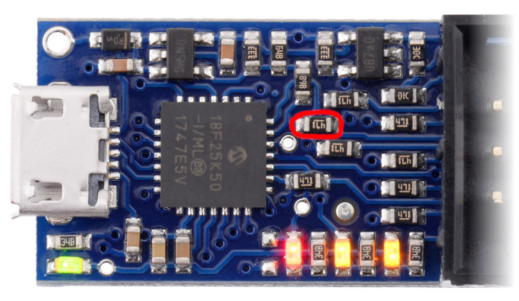
I have spent 2 days poking around the situation with a scope and logic analyzer. I checked wiring 15 times, powered the Arduino from Pololu Programmer or independently, etc etc and all of the combinations. I found, that using the logic analyzer, I can perfectly follow an avrdude session (just reading fuses to keep it short) hex-byte by hex-byte on the lot of Nanos which do work.
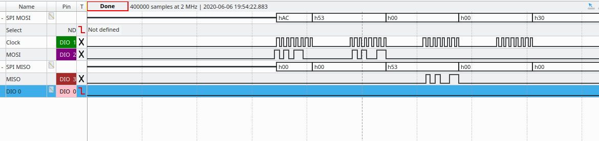
However. on the ones which don’t work, I can see data on the MOSI line (AC, 53, 00, 00) but there is “no clock” on SCK. So the Nano doesn’t realise it is being talked to and therefore doesn’t reply.
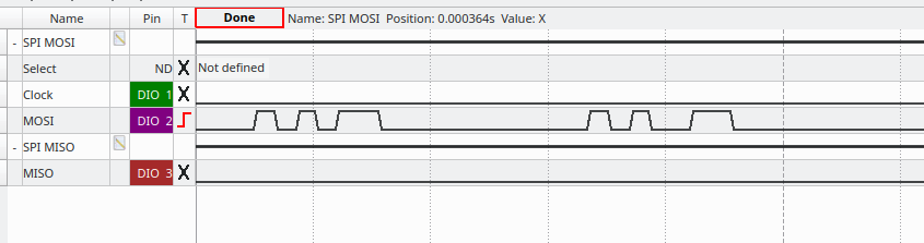
Why is there no clock? If I look with a scope rather than a logic analyser I can see that the Pololu AVR Programer is trying to drive the clock, but it only manages ~0.1V of square wave.
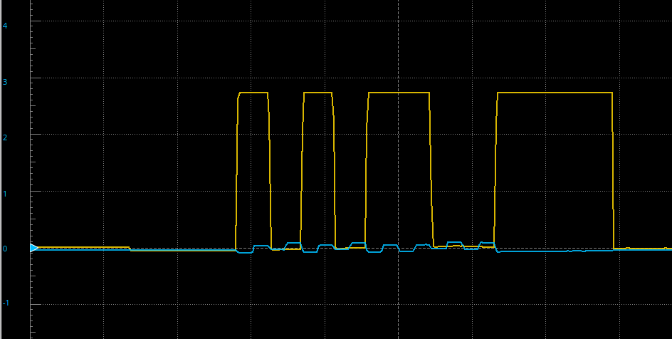
But if I remove the 6pin header plug and measure directly on the end of the cable, it’s fine. Like there is a short on the Nano or in the circuit. Except there isn’t. It turns out that it’s the BUILTIN_LED (digPin13) which is configured as an output somewhere in the running code, and fighting the clock. So why is it doing that when it is being programmed? It’s not supposed to be running code and it should be putting its digital pins into tri-state? I proved that it’s running code, by uploading a sketch which sets the Pin13 SCK as an input. The behaviour changes massively, and we now have a clock, but it still doesn’t answer.
The plot thickens…
Looking more closely at the other signals it tuns out that the lot of Nano’s which don’t work, don’t recognise the RESET signal from the programmer. Therefore they don’t stop running, fight the clock with their BUILTIN_LED output, and can’t possibly enter programming mode (for more than one reason).
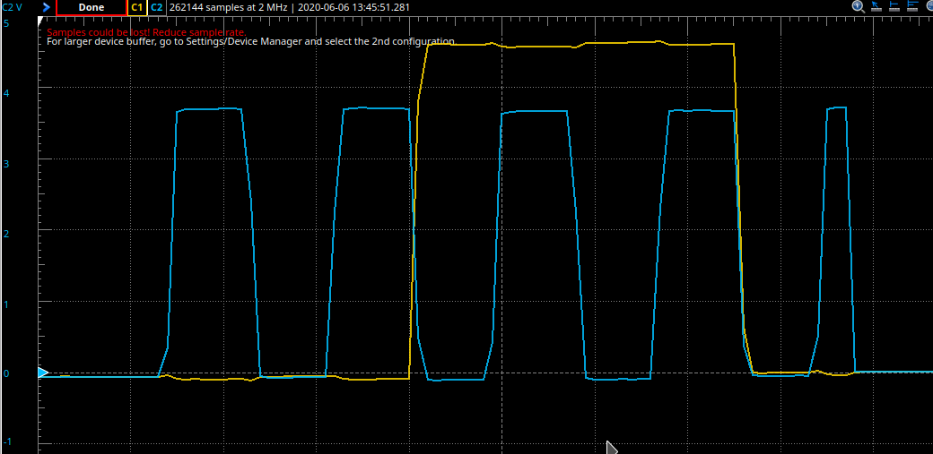
The scope shows that the RESET is a nice 0.1V → 4.9V range when I just plug straight into the header cable without connecting it to the Ardunino. But if I connect to the Arduino, the range drops to ~1.6V → 4.9V.
According to section 28.2 in Atmel’s 328p datasheet the valid maximum for a logic low on the reset line is 0.1Vcc so 0.5V. We are way above that, at ~ 0.3Vcc. No wonder it is not resetting reliably. The voltages are actually very similar on both the working and non-working lots of Nanos, but we are in “undefined” territory here, so any small difference could easily make it tip one way or the other.
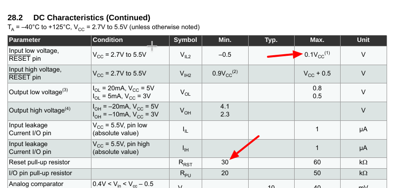
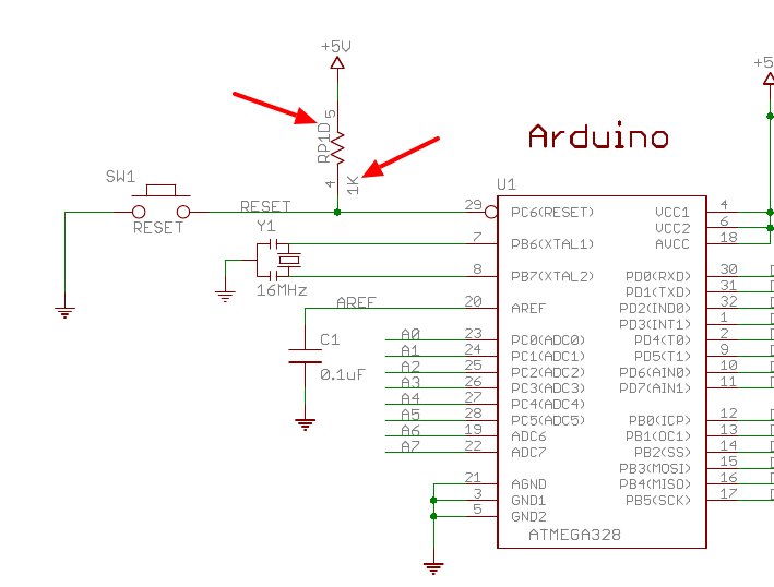
The same section in the Datasheet recommends a 30-60kOhm pullup for the reset line. All my Nanos (both lots) are using a 1kOhm! This is both according to the schematic and measured in the circuit as that. So this is “not the Pololu Programmer’s fault”, because Arduino have designed the Nano with a RESET pullup which is 30x smaller than the minimum recommended value. Perhaps the reason they did that was to compensate for the capacitor hack on the DTR line of the USB chip and keep a reasonable time constant? Could have just used a smaller cap? So there is also a significant cap charging response on that reset line as well. Anyway… It’s not great.
I experimented with the 6 pin flat cable not plugged into the Nano and a 22kOhms up to the Vcc pin (with Vcc Output=enabled on the Pololu). We get very nice signals. At less than 10k we are entering dodgy territory and at 1k it’s a disaster.
Oh, and I worked out that if I press the manual reset button while connecting with avrdude via the Pololu programmer, then… it works fine. And the scope/logic analyser show proper reset levels => proper clock => the AVR answers => the “fuse read operation” works just fine. – Note: I realise that this is a) not practical and b) not good for the Pololu Programmer to hard clamp it’s RESET output like that.
I think the fact that I have Chinese clones is probably irrelevant here, since the official schematics have that 1k pullup (actually it’s one quarter of a 4x1k resistor array).
So what do you suggest?
Is the Pololu Programmer not reliably suitable for Nanos?
Is there a mistake in my thinking? – You should easily be able to reproduce the out-of-spec voltage range on the Pololu RESET output by poking a 1kOhm into the RESET and VCC pins on the end of the flat cable with 5V Vcc output enabled. I get ~1.5V → 4.9V. What do you get? Note: I re-emphasise that am not saying the Pololu design is wrong. It is just that it may not be compatible with the 30x out of spec RESET pullup on the Nano. It looks like the Uno uses a 10kOhm in that place with the same 100nF cap on the DTR line. That should (just about) work fine with the Pololu. Why they chose a 1k on the Nano is beyond me – probably just because they had a spare 1k on one of the arrays?
Have I missed a trick? - I did think of using a couple of transistors to amplify the Pololu Programmers pull down capacity on the RESET line. – would probably work, but would be messy. – Update I breadboarded this and it works 100%. Lovely 0V => 5V range on the RESET line now. The Nano resets fine and ICSP sessions work every time and with all Nanos I ave access to. Going to make a more permanent version to splice into the 6pin flat cable.
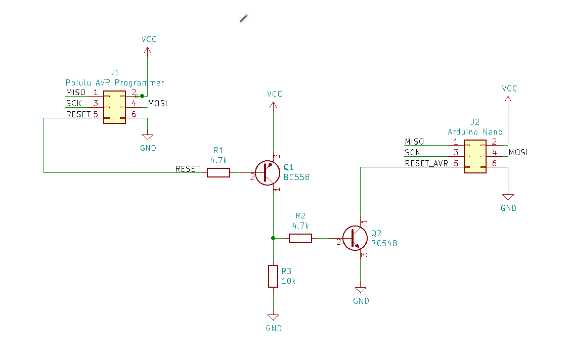
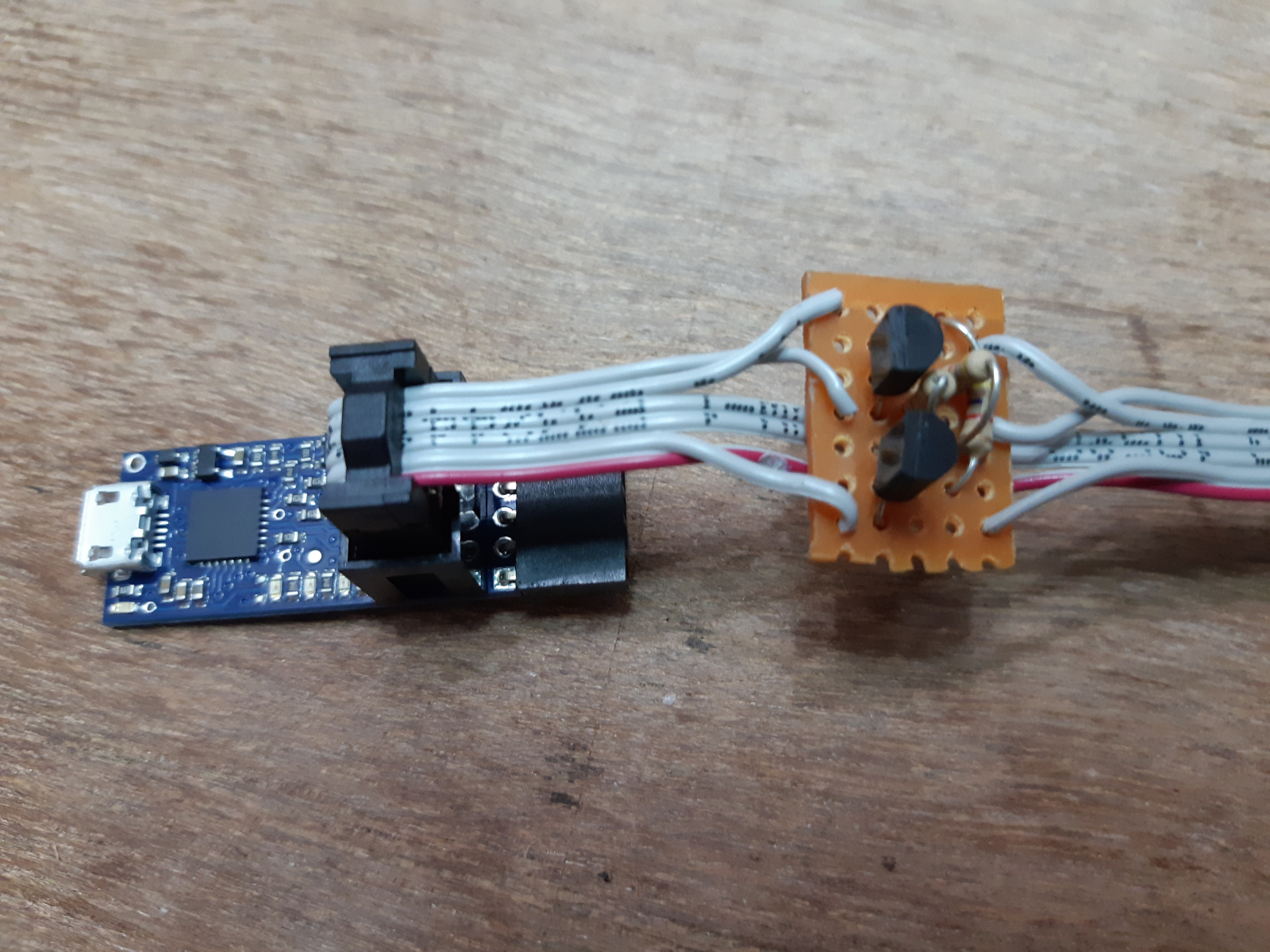
It’s not super pretty. But it works 100% better. Can anyone suggest some other solution?
BTW what are the “STK500 hardware/software version” settings in pavr2gui? I found no docs on those.
Many Thanks