I know I’ve asked this question before, but I can’t find the answer on the forums. The schematics suggest that it might be possible to shut down the 3PI or the LV-168 with a logic-level signal on BTN1 or BTN2 of the power IC. If so, what are the characteristics of these inputs and what voltage level or current source/sink is required?
The 3pi does not have the auto shutdown feature. If you are interested, I can look up the resistor to which you could solder a little transistor circuit. On the LV-168, there is a shutdown pin that is connected through 10k ohms to a transistor base, which is also pulled down with a 10k resistor. The pin is next to the power button, and it’s labeled “off”; connecting the pin to an I/O line and setting it high will turn off the board.
I experimented with my 3pi and found that by briefly connecting a 1K resistor between the round pad of J20 and Vbat turns off the robot.
J20 can be found on the bottom of the robot. It is mostly blocked from the topside by C2b. To find J20, flip the 3pi upside down, with the caster towards the bottom. J20 is the two holes just below the right wheel, very near the blue LED.
Connecting the square pad to Vbat via a 1K resistor seems to turn the robot on, although I don’t see how the robot could do this on its own.
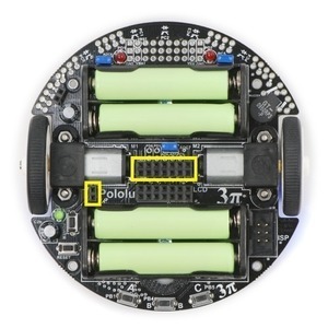
It sounds like Dale isn’t talking about J20, but his post did remind me that you can indeed turn the 3pi off by pulling one side of J20 to VBAT. J20 isn’t labeled or populated, but it’s the parallel pushbutton connection for the expansion board. It’s highlighted in the picture below (the smaller rectangle below the left motor):
The side to pull up is the one closer to the motor. A small PFET or PNP transistor from that pin to VBAT should work, and I think you could connect the base or gate straight to a 5V I/O line. I haven’t tried it, and with VBAT potentially going to almost 5.5V and the I/O line not driving all the way to 5V, you might be close to not being able to turn the transistor off well enough. You could help it out by pulling he gate or base toward VBAT, but make sure you use the VBAT that’s past the power circuit (as opposed to the charging port, which connects directly to the battery and isn’t labeled VBAT)–otherwise, you could weakly power the 5V part through the resistor and I/O pin.
By the way, what Dale was doing was probably shorting out power. Square pads are all ground, so connecting anything to a square pad would be shorting it to ground. I don’t think an extra 5mA would do anything though, so are you sure your resistor was 1k, Dale?
Yes, that was my mistake about J20. I assumed it was the pads that were paralleled with the power button due to their proximity to the button and what I could figure out was going on from the schematic. I see now in the bright light of morning that they are just alternate mounting holes for C2b, similar in configuration to C7b. That’s a nice trick in case you need to use a slightly different style of capacitor in the future.
Attempting to reproduce my turn-off trick this morning with a 1K resistor doesn’t seem to want to work. I must have been using a much smaller value instead and shorting out the battery. Looking closer, I see that I was shorting it to the connection between the two battery holders, or Vbat/2. In any case, the blue LED was dimming slightly before going out. I can no longer recommend this method for turning off your 3pi robot!
Thanks for clearing this up for us, Jan. I’ll try to come up with a few pictures of the auto-shutoff circuit you suggested and get them posted back here soon.