I’m using the nice little ATtiny26 project board from Pololu for a couple of projects, and I’m wondering about the on-board LP2950 regulator.
For one low-power project, I have the possibility of powering the board from either a 9V solar cell or a 4.8V NiCd backup battery. If I connect the 4.8V battery to the regulator output (Vcc) and leave the regulator input terminal effectively open (in other words, a diode in series with the solar cell), does anyone know what will happen? The LP2950 data sheet does not give any insight into this situation. I expect that the regulator can tolerate this but it might add some unnecessary current drain.
By the way, I really like the board design. If only the ATtiny26 had a bit more memory…
We don’t have any information beyond what is in the datasheet. By the way, there are a few manufacturers of the part, and your board probably has the one from On Semiconductor. Did you look at the datasheet from that company?
I’m happy to hear you like that prototyping board. Can you tell me what you like about it? I’m especially curious because we find boards like that handy internally, but it doesn’t seem to sell well. We even had some ATmega8 versions made, but we never sold them (there were some other factors besides the ATtiny26 board not doing well, such as the mega168 coming out and the move to 6-pin ISP connectors). Is the RS-232 option useful? We’re thinking of doing something with USB, but it seems difficult to keep the price low enough. If we had a board with a similar form factor but with a mega168 or mega328 with an integrated programmer and USB-to-serial adapter for around $30, would that be compelling?
I don’t know about Jim, but I’m frequently building little one-off AVR+programming port+USB/Serial adapter boards for people in my lab for sensor evaluation or data acquisition or such. We would probably buy a few, especially if the footprint was compact.
Recently I’ve been using ATMega324p’s (2 UARTs baby!) and this board from SparkFun.
I’ve been looking at that chip lately (for a higher-I/O-count Orangutan). Having the ATmega1284P upgrade option (16k SRAM!) seems nice, too. Too bad the part isn’t supposed to be out for another half a year.
The 164P/324P/644P line has been very nice to work with (you can never have too manu UARTs), but watch out what you wire to what for initial startup. The JTAG fuse comes set, which makes some pins start up set high.
Not realizing this we designed our main board which uses the pushbutton power switch with one of these connected to the OFF pin. I spent the better part of a day trying to figure out why the board wasn’t turning on. Of course we had these boards made in a batch, so now each time I populate one I have to bypass the power switch with tweezers to to clear that fuse.
Edit 3/30/09 ignore the first paragraph that follows – I made some mistake. Connecting +5.0 volts to the regulator output on the ATtiny26 board, while leaving the regulator input floating, does not result in excessive current draw. There is a small current draw increase at 5.2 V (less than 1 mA). I suspect that no long term damage should result from this misuse, as long as one does not exceed other component ratings.
Well, I connected a 4.8V source to the regulator output, with the regulator input floating and discovered that this is a bad idea. My power supply current-limited at about 1 amp. Fortunately, I disconnected it quickly enough to prevent any obvious permanent damage to the regulator. What puzzles me is that the regulator encounters this situation every time the external source is switched off and there are capacitors in the circuit that must be discharged, so there is some reason to think that such a transient backflow is not damaging. Oh well. I can always use diodes to switch between solar and backup supply, but I thought I could float charge the battery without such trickery.
What I like about the ATtiny26 board is the convenient arrangement of two ports with access to power and ground at several points, coupled with the well-laid out prototyping area. I especially like the plated through holes, which are fantastic for prototyping if you have to remount components several times. The board seems to tolerate many soldering/desoldering cycles without obvious damage, and there is no tendency for solder to bridge between pads.The RS232 output is dated, of course and in fact I’m using the board with a USB to serial converter. I think a similar board, with perhaps an ATmega168, a USB programmer and USB serial output would be popular, especially if one could figure out how to put a memory stick/DOS file system like the Vinculum on it (think data logger). I would certainly buy a few at $30.
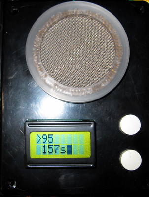
My most recent project with the ATtiny26 board is a Geiger counter. It features an internal 500V power supply (2 mA total draw!), an 8x2 LCD display and USB serial port emulator output (which also powers the entire unit at 8 mA total). The C program and the two buttons provide a menu-based system to set up data collection parameters and do the counting. The program currently occupies 2026 out of 2048 bytes of program memory. See below for the exterior appearance. The unit is currently monitoring the cosmic background radiation in my office (95 counts in 157 seconds). I could post the entire project if you think it would help sales of the ATtiny26 board
I do intend to buy a few more – the sale price is very attractive, so be sure and save me a couple!
Jim,
That sounds like a fun project; whether or not it helps us sell the boards, I’d be interested in hearing more about it! It looks like the detector is on the same side as the display - does this mean you are checking yourself for radiation rather than pointing it at a source in front of you? Where did you get your Geiger tube?
Can you try doing the regulator test again? I do that sort of thing all the time, and I have had no problems. I just tried taking a regulator part (not on a board) and applied from 4.5 to 6 volts on the output, and I got no detectable change in current (power supply has 0.01A resolution).
Thanks for checking on the regulator – maybe I shorted the power supply while hooking things up. I had to jump! I’ll repeat that test to see if I made a mistake.
Since there is some interest, my Geiger counter is based on a circuit described by Tom Napier in Circuit Cellar #184, November 2005. His circuit’s most attractive feature is a very efficient and rather ingenious high voltage generator based on an LMC555 timer, a small inductor and a couple of transistors. There is one error in the published circuit: pin 6 of the LMC555 has to be connected to ground.
I’m primary interested in cosmic rays, solar flares and other sources of low-level radioactivity, which require long counts to accurately measure – for example my partner is an archaeologist and does carbon dating. So, I used the more sensitive “pancake” Geiger tube LND7313, purchased directly from the manufacturer LND Inc. (about $130) rather than the one Tom used (the smaller and less sensitive LND712, available from imagesco.com for about $75). Both have a thin and very delicate metalized membrane for measurement of alpha radiation. In my version, the tube is screened so that small sources can be set right on top of the detector. Alpha particles penetrate only about 1/2 inch of air. Beta and gamma radiation are much more penetrating so the direction the tube is pointing is less important (and is actually irrelevant for gamma radiation). Tom’s circuit used a PIC programmed in assembler, so I rewrote everything in C from scratch. I use all but two I/O pins.
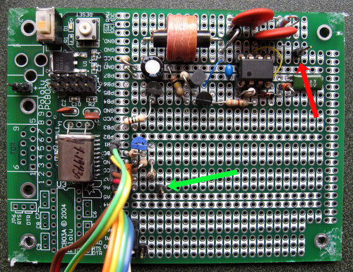
I’ll post the code and schematic after I come up with an electronic version. The board is shown below. The HV generator is top right, leading to the connector for the 500V tube bias (red arrow). The counter input (INT0) is marked with a green arrow. The rainbow cable leading off screen goes to the two pushbuttons and the LCD.
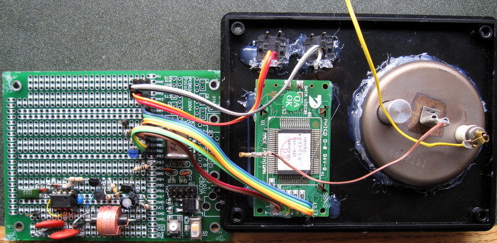
Finally, an “exploded view” after removal of the case reveals my quick and dirty hot glue mounting technique: