My first use of Microchip Studio 7 to ATtiny13A. - My first use of an AVR actually.
I have AVR on circuit board. I can program the AVR with the 6 wire (MOSI, MISO, SCK etc) . The problem I have is when certain components are connected, I get a failed to launch program just after the compiler output:
Build succeeded.
========== Build: 1 succeeded or up-to-date, 0 failed, 0 skipped ==========
I think I get a time out error during the ‘Loading Executable (14%)’ stage.
I can solve this by disconnecting the link to the servo’s MOSFET driver but this will be inconvenient when I move the build to a finished unit. I’d still like to be able to program the AVR ‘in situ’ as there are some ‘select on test’ parameters that will need changing.
I can understand that connecting a 15mA load to a MISO pin or the output from a voltage difference amplifier (I tried these) would impact on the programming signals (I’ve moved these away to PINB3 and PINB4).
I have to use PINB1 for the servo as I want to use the PWM on OC0B (MISO).
I have a 10M resistor from PINB1 to Vcc and a 10K resistor from PINB1 to the input gate of my MOSFET.
I’ve tried increasing the 10K resistor to 100K but that still seems to have an adverse impact on the programming communication. If I increase it further to 1M, the MOSFET does not switch on to drive the servo.
Could anyone aim me at a spec sheet that defines what I may and may not connect to the MOSI / MISO etc pins in parallel with the Pololu so I can design a circuit that will allow ‘in situ’ programming.
It’s not a big issue but one I’d like to understand so I may avoid in the final build.
I have tried a 10uF cap across the AVR pcb supply rails. Am I missing some capacitors on the data pins?
I’ve been thinking about my problem.
It must be a power supply issue. I have no problem if I disconnect the servo but leave the servo’s MOSFET harness in place so it’s got nothing to do with the resistive 10K through 10M to Vcc holding the MISO pin high.
My target environment is powered by 4 x AA batteries. The AVR voltage is derived from this via a Shottky diode (so as to block this from an external emergency supply) and then a standard 1N4004 to drop the voltage to a nominal 5.1v.
I plan to move the servo away from MISO as I don’t want it to drive incorrectly, stall, strip the gears or damage the attached mechanism. I’ll swap it back for the 15mA load connected to PINB0
I plan to add another dropper diode so that the Pololu will reject the presented voltage at 4.4v. I’ll add an external power jumper on the AVR power line at a fat regulated 5v and I’ll retest the unit.
Doing this will be safer for the AVR (I’ve read your forum about blowing fuses if the power is not spot on) and the servo.
I’ll post an update if I resolve my issue but I’d still like to know what current drain on the MISO pin the Pololu can handle. As in, my 15mA load would look like a 330R connected between PINB1 (IC pin 6) and ground. Is this maybe why the LEDs on the ATTiny13 dev board I purchased are hooked up to Vcc?
I have a solution.
I’m stuck with using PINB1/MISO as I need the OC0B for my servo.
The challenge was to disconnect the servo from this pin while the Pololu was programming. I tried to sort something out with diodes to try to separate the MISO signal from the Pololu from the servo drive pulses on PINB1 but didn’t get far as any diode would distort the signal back into MISO and the Pololu wouldn’t play ball.
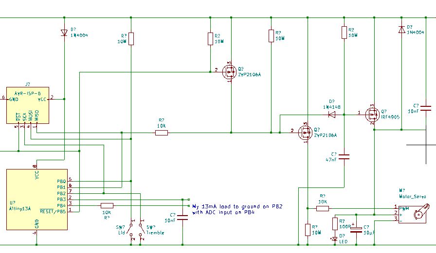
Then I realised that the Pololu holds the Reset line is low for a while so I used this to drive another MOSFET to tie my servo control MOSFET high (off) for the duration of the reset signal. This works a treat and the servo doesn’t get any pulses during Pololu programming now. No need to do anything special now to programme my ATtiny13a in situ.
I’ll try to attach a circuit diagram of my servo MOSFET harness if anyone is interested…