Hi,
I am Soumya, a hardware design engineer. For one of our client projects where we need to run the stepper motor NEMA17-13-04PD-AMT112S, we have decided to go ahead with the Polulu TB67S128FTG Carrier Board ( Pololu item #: 2998 ).
-
However, I wanted to know how we would mount this board to our PCB ? I think we have to first solder the male headers to the Polulu board; then we will solder the mating female headers to our custom PCB and then we will mount the carrier board to our PCB. Is this the best way of assembling this driver board ? How robust will this assembly be ?
-
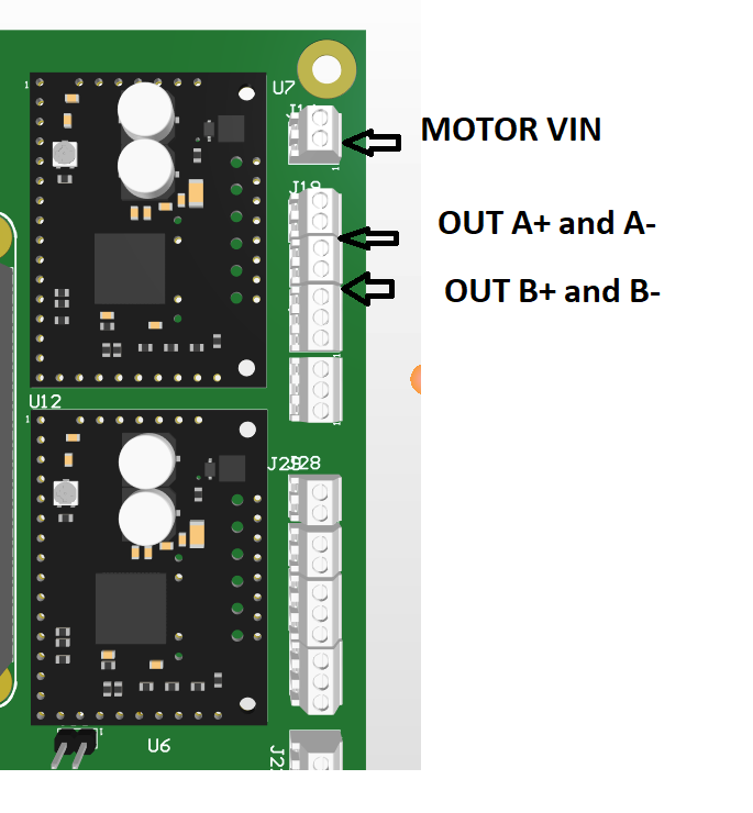
We are planning to operate the motor at 24V. I am a bit skeptical about the performance of the board given such an assembly where a 24V supply has to go through two connector surfaces to reach the module. Same concern for motors output as well. Will the current and voltage get hampered ?
Do let me know as soon as possible. I have sent a mail as well with the same email id.
Thanks.
Hi.
Our TB67S128FTG Stepper Motor Driver Carrier could be mounted with just female and male header pins like you mentioned. If you connect all the 0.1" headers around all four sides I expect this would make a fairly stable connection. So unless your application involves lots of vibration or something like that, headers should be sufficient for mounting.
For the power and motor connections you could use headers, terminal blocks, or your own wires and connectors. The included header pins are rated for 3A per pin, so they should be sufficient for your 1.3A motor. I do not expect any issues to arise from using a 24V supply with the header pins or multiple connectors as long as they are all soldered well and making god connections. For reference, many of our smaller drivers are used on RAMPS kits that people modify to run at 24V, and they connect through just header pins.
-Claire
Hi Claire,
Thanks for your swift reply. I had just another query - What is the function of the ground pad which is exposed in the bottom of the PCB (below the driver IC) ? If we go ahead and use the male-female header pins, then this pad will not be used/cannot be soldered to anything. So, is there any other reason for having this ?
The exposed ground pad is for attaching an optional heatsink. Since your motor is only rated for 1.3A and the carrier should be able to handle around 2.1A without additional cooling, you probably do not need to worry about attaching anything to that pad.
-Claire