Are the matlab motor efficiency calculations for the 12V motor correct?

I am using the listed motor and the accompanying matlab code to calculate motor efficiency in hopes that I can find the reason for discrepancy with my simulations. I assumed the efficiency would be somewhere around 80% but this program is giving me a maximum of 30% which I feel cannot be correct. I entered the following:

Please enter the stall torque in oz-inch [17]: 240
Please enter the stall current in mA [700]: 5600
Please enter the rated voltage in Volts [6]: 12
Please enter the free run currennt in mA [40]: 300
Please enter the free run speed in RPM [290]: 130

This results in the attached image which indicates an efficiency of less than 30%. This seems incredibly strange. Please advise.

1 Like

Hello.

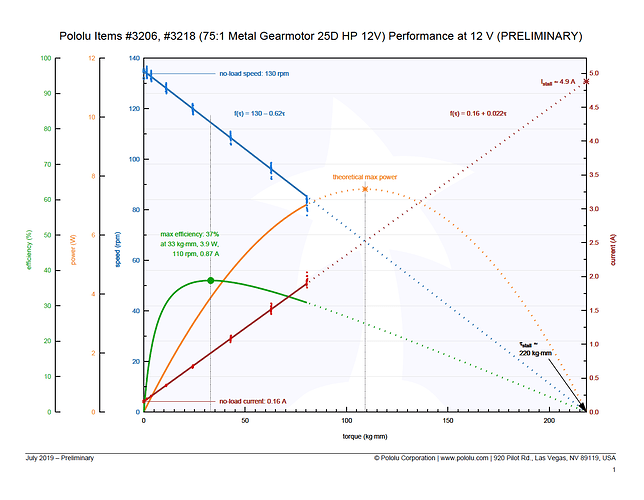
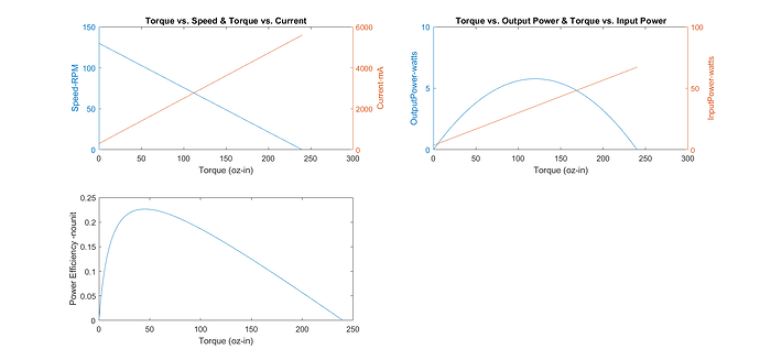
We just finished preliminary performance tests of that gearmotor, and here are the resulting performance graphs:

In general, small brushed DC gearmotors like these will have typical peak efficiencies in the range of 30% to 40%. For additional datapoints, see the performance graphs we have published for our micro metal gearmotors and 20D metal gearmotors. Out of curiosity, what is your expectation of ~80% peak efficiency based on?

-Nathan

1 Like

I think I based it on some false assumptions about larger motors which show higher efficiency: https://www.energydepot.com/RPUcom/library/MISC003.asp

This has been incredibly helpful, thank you!

Just wanted to do a quick update and say that you may want to put a disclaimer with the MATLAB script included in the motor description as the curves definitely do not match this. Thank you for this graphic though, this has really helped a lot of things make sense.

I also wanted to verify that I’m reading this correctly. The highest load you put on this was approx 80 kg-mm, resulting in 85 RPM, a current demand of almost 2A, and an efficiency of 30%. This efficiency is the percentage of electrical power (like what the reading of a power supply might state) that has been converted to mechanical power. Correct?

This is also at 12V. I’ve been using the encoders for speed feedback. If I tell my craft to operate at, say, 60RPM the motor controller should modulate the amount of voltage I see. This would assumedly affect the efficiency curves but I’m curious by how much. We don’t have a direct measurement of load, but for our 10 trials at 60 RPM the average pull of each motor was 0.264A. Would we use the load as a guide?

That MATLAB script is maintained by one of our customers and, more importantly, its accuracy depends on the accuracy of the motor specifications used as inputs. We are currently in the process of more accurately characterizing our motors and updating the specifications on our product pages (the graph we posted is a result of that effort). In general, our older, less accurate specifications tend to be on the conservative side, hence the lower efficiency when using them.

Yes, you are reading the graph correctly, and the efficiency provided is the mechanical power output of the motor divided by the electrical power input.

In general, the efficiency is largely dictated by power loss due to internal friction, which is independent of the voltage, so the peak efficiency and efficiency at max power won’t change much as a function of voltage. However, the torques at which these points occur will change as a function of the voltage.

If you want to estimate the efficiency curves at different voltages, you can use 12V data I shared previously to help. Note that for an ideal motor, changing the voltage will just change the y-intercept of the speed-vs-torque line (that parameter is directly proportional to the voltage). The relationship between current and torque would be independent of the voltage, as would the slope of the speed-vs-torque line. In reality, lowering the voltage generally reduces motor heating, and motor performance is negatively affected by heat, so empirically measured motor parameters will often show a slight voltage dependence even where there should be none. If the data could be taken in a way that let the motor stay cool throughout the measurements, those voltage dependencies would generally go away.

-Nathan

I suspected as much but it’s good to get this confirmed. Thank you!

Hey Nathan,

I think I know the answer but I wanted to ask. I’m looking at our readings for current during our runs, and for our speeds we’re getting, for example, 4.25V @ 54 RPM and current of 0.17A per motor. You said the following:

If you want to estimate the efficiency curves at different voltages, you can use 12V data I shared previously to help. Note that for an ideal motor, changing the voltage will just change the y-intercept of the speed-vs-torque line (that parameter is directly proportional to the voltage). The relationship between current and torque would be independent of the voltage, as would the slope of the speed-vs-torque line.

Does this mean if I wanted to back calculate the torque based on the motor constant, speed, and current, I would use the C = 0.16+0.022T line? Or would the y-intercept be 0.16*whatever fraction of 12V we’re using? I say this because we have many low-speed trials where each motor is reading below 0.16A according to arduino. This also matches fairly well from what I’ve seen on the power supply, giving a total of 0.17A when the motors are pulling say 0.085A.

Just trying to sanity check some things. We’re now getting 50% error when I assume, say, an intercept of 0.06A and the load is only 0.17A per motor @ 54RPM and like 4.5 V.

In an ideal motor, the torque output would be proportional to the current and independent of the voltage, and the free-run current would be zero. In a real motor with non-zero free-run current, that current is the result of things like internal friction, which can vary with speed and hence add some voltage dependence. We just posted some datasheets for our 37D motors with testing results for the same motors at their rated voltage of 12V as well as at 6 V. You can compare the 6V and 12V graphs to see how the current equations changes with voltage. In particular, you can see that the free-run current does go down some as the voltage goes down, but it is not proportional. Meanwhile, the slope of the current line is mostly unaffected by the voltage.

If you want the most accurate model for your motors at some voltage, you should probably use the actual free-run current you are measuring at that voltage combined with the slope from our published 12V graphs.

By the way, 54RPM seems a little high for the a 4.25V input for the motor (I would expect about 46RPM). How are you controlling the voltage to the motor and how are you measuring the speed?

Hey Nathan,

Thanks for your response on this. For the sake of brevity, let me just add my approximated readings for voltage/current of my motor under no load conditions by voltmeter:
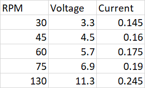
image

I learned another valuable lesson here, which is to always verify your ground truths before proceeding with either data collection or analysis. I find the current draw changes somewhat unsurprising because this motor has been through a good amount of use. The Arduino/Motor Driver combo we were using to read this was giving us wrong voltage values because we were running the power supply at a higher voltage due to some earlier issues (which are now corrected). The Arduino readings are as follows for the exact same motor under the exact same conditions:
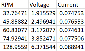
image

We are using the Dual MC33926 Motor Driver for taking in the power supply and feeding it to the motors. Arduino is used solely for data collection and feedback control via encoders and is powered by USB. The power supply was run at 27.5V and we’re going to drop that down to 12V and observe the difference. I think we were mistaken about exactly what was being measured by the A0, A1 pins.

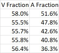
What I’m trying to currently solve is how to fix this. So far the Arduino voltage displays a very predictable fraction of the real voltage, but the current seems to display no such relationship.
image

In either case, I will update if we find anything. Let me know if you have any insights.

Edit: Solved the voltage mystery and have one additional question about the current one.

Voltage was a simple conversion issue in Matlab where we left the old voltage constant in. It now converts to well within range of the measured values via voltmeter.

For current, I want to make sure I understand the motor controller library. It says the following in the c++ code:

/ Return motor 1 current value in milliamps.
unsigned int DualMC33926MotorShield::getM1CurrentMilliamps()
{
  // 5V / 1024 ADC counts / 525 mV per A = 9 mA per count
  return analogRead(_M1FB) * 9;

The commented items there refer to internal calculations from the library/architecture, yes? In other words, if we use our Arduino command:

current1 = md.getM1CurrentMilliamps()

The variable will store the approximated current in milliamps, no additional calculation required, correct? Also in the user manual it states that “The pin voltage is roughly 525 mV per amp of output current.” In that calculation, I understand it means approximately 9 mA of resolution in reading the current, correct? Or rather, 1 ADC count of resolution.

I think I will return to my lab and run our power supply at 12V and report findings.

Edit2: After reducing the power supply to 12.5V, I noticed that the current values are roughly half of those I obtained at 27V. It’s not giving the current of the motor draw, it’s giving some sort of current from the power supply, but definitely nowhere near the actual value.

Edit3: I am stumped. I have switched out both the Arduino and Motor Shield individually (we have backups) because I thought it was perhaps a burnout from use. The motor continually displays the same current at 130 RPM, 14V power supply to the shield: about 0.2-0.22A. This is inline with your motor performance curve. Yet the draw on my Arduino output is the following:

Dual MC33926 Motor Dual MC33926 Motor Shield
RPM1: 0	RPM2: 0	k1 V: 360	k2 V: 360	M1 current: 585	M2 current: 513
RPM1: -109	RPM2: -122	k1 V: 326	k2 V: 349	M1 current: 72	M2 current: 45
RPM1: -122	RPM2: -118	k1 V: 354	k2 V: 340	M1 current: 45	M2 current: 45
RPM1: -122	RPM2: -122	k1 V: 354	k2 V: 348	M1 current: 27	M2 current: 54
RPM1: -126	RPM2: -126	k1 V: 355	k2 V: 351	M1 current: 54	M2 current: 36
RPM1: -126	RPM2: -122	k1 V: 360	k2 V: 350	M1 current: 27	M2 current: 36
RPM1: -118	RPM2: -118	k1 V: 356	k2 V: 354	M1 current: 45	M2 current: 45
RPM1: -122	RPM2: -126	k1 V: 355	k2 V: 356	M1 current: 36	M2 current: 54
RPM1: -126	RPM2: -126	k1 V: 358	k2 V: 355	M1 current: 54	M2 current: 45
RPM1: -122	RPM2: -126	k1 V: 358	k2 V: 355	M1 current: 36	M2 current: 45
RPM1: -126	RPM2: -126	k1 V: 360	k2 V: 353	M1 current: 54	M2 current: 45
RPM1: -126	RPM2: -130	k1 V: 358	k2 V: 357	M1 current: 36	M2 current: 36
RPM1: -126	RPM2: -122	k1 V: 360	k2 V: 354	M1 current: 27	M2 current: 45
RPM1: -126	RPM2: -126	k1 V: 360	k2 V: 355	M1 current: 45	M2 current: 36
RPM1: -126	RPM2: -126	k1 V: 360	k2 V: 353	M1 current: 54	M2 current: 27
RPM1: -126	RPM2: -126	k1 V: 360	k2 V: 357	M1 current: 36	M2 current: 54
RPM1: -126	RPM2: -126	k1 V: 358	k2 V: 354	M1 current: 9	M2 current: 45
RPM1: -126	RPM2: -126	k1 V: 360	k2 V: 352	M1 current: 54	M2 current: 36
RPM1: -126	RPM2: -126	k1 V: 360	k2 V: 356	M1 current: 36	M2 current: 45
RPM1: -126	RPM2: -126	k1 V: 358	k2 V: 356	M1 current: 54	M2 current: 45
RPM1: -126	RPM2: -126	k1 V: 360	k2 V: 354	M1 current: 45	M2 current: 36
RPM1: -126	RPM2: -130	k1 V: 355	k2 V: 359	M1 current: 45	M2 current: 27
RPM1: -126	RPM2: -122	k1 V: 360	k2 V: 354	M1 current: 45	M2 current: 54
RPM1: -126	RPM2: -126	k1 V: 356	k2 V: 355	M1 current: 27	M2 current: 27
RPM1: -126	RPM2: -126	k1 V: 360	k2 V: 355	M1 current: 45	M2 current: 54
RPM1: -126	RPM2: -122	k1 V: 360	k2 V: 355	M1 current: 45	M2 current: 27
RPM1: -126	RPM2: -126	k1 V: 360	k2 V: 353	M1 current: 36	M2 current: 45
RPM1: -46	RPM2: -97	k1 V: 185	k2 V: 218	M1 current: 45	M2 current: 18
RPM1: -97	RPM2: -84	k1 V: 273	k2 V: 255	M1 current: 18	M2 current: 45
RPM1: -97	RPM2: -101	k1 V: 282	k2 V: 280	M1 current: 45	M2 current: 45
RPM1: -105	RPM2: -105	k1 V: 303	k2 V: 302	M1 current: 45	M2 current: 36
RPM1: -109	RPM2: -109	k1 V: 325	k2 V: 314	M1 current: 45	M2 current: 54
RPM1: -113	RPM2: -118	k1 V: 329	k2 V: 331	M1 current: 18	M2 current: 45
RPM1: -118	RPM2: -118	k1 V: 344	k2 V: 334	M1 current: 36	M2 current: 45
RPM1: -122	RPM2: -122	k1 V: 352	k2 V: 342	M1 current: 54	M2 current: 18
RPM1: -122	RPM2: -122	k1 V: 354	k2 V: 346	M1 current: 45	M2 current: 36
RPM1: -126	RPM2: -126	k1 V: 355	k2 V: 353	M1 current: 27	M2 current: 27
RPM1: -126	RPM2: -126	k1 V: 355	k2 V: 354	M1 current: 27	M2 current: 36

The current output is supposed to be in millivolts and the k value is a number out of 400 where 400 is the power supply number. 360/400*14V = 12.6V which is ballpark close. 27mA is not enough to power a motor… it’s barely enough to power the encoder! There is seemingly no difference I can make, other than to change the power supply voltage. This seems to affect the number and the number is directly proportional to the power supply voltage. Something interesting is if I change the motor direction from -k to k, the exact same speed comes out as follows:

Dual MC33926 Motd
Dual MC33926 Motor Shield
RPM1: 0	RPM2: 0	k1 V: 360	k2 V: 360	M1 current: 630	M2 current: 513
RPM1: 109	RPM2: 122	k1 V: 330	k2 V: 346	M1 current: 63	M2 current: 63
RPM1: 122	RPM2: 118	k1 V: 355	k2 V: 340	M1 current: 54	M2 current: 81
RPM1: 122	RPM2: 126	k1 V: 354	k2 V: 348	M1 current: 63	M2 current: 45
RPM1: 122	RPM2: 126	k1 V: 353	k2 V: 352	M1 current: 72	M2 current: 81
RPM1: 126	RPM2: 126	k1 V: 360	k2 V: 351	M1 current: 54	M2 current: 45
RPM1: 126	RPM2: 126	k1 V: 358	k2 V: 351	M1 current: 54	M2 current: 45
RPM1: 126	RPM2: 126	k1 V: 358	k2 V: 352	M1 current: 63	M2 current: 27
RPM1: 126	RPM2: 126	k1 V: 360	k2 V: 350	M1 current: 63	M2 current: 36
RPM1: 126	RPM2: 126	k1 V: 360	k2 V: 350	M1 current: 99	M2 current: 45
RPM1: 126	RPM2: 130	k1 V: 358	k2 V: 354	M1 current: 54	M2 current: 81
RPM1: 126	RPM2: 126	k1 V: 357	k2 V: 355	M1 current: 81	M2 current: 54
RPM1: 126	RPM2: 126	k1 V: 360	k2 V: 352	M1 current: 81	M2 current: 72
RPM1: 130	RPM2: 126	k1 V: 360	k2 V: 350	M1 current: 45	M2 current: 63
RPM1: 126	RPM2: 130	k1 V: 357	k2 V: 355	M1 current: 54	M2 current: 27
RPM1: 126	RPM2: 126	k1 V: 357	k2 V: 357	M1 current: 81	M2 current: 63
RPM1: 126	RPM2: 126	k1 V: 360	k2 V: 351	M1 current: 18	M2 current: 63
RPM1: 126	RPM2: 130	k1 V: 357	k2 V: 352	M1 current: 54	M2 current: 54
RPM1: 126	RPM2: 130	k1 V: 360	k2 V: 358	M1 current: 54	M2 current: 81
RPM1: 130	RPM2: 130	k1 V: 360	k2 V: 356	M1 current: 81	M2 current: 54
RPM1: 130	RPM2: 130	k1 V: 360	k2 V: 353	M1 current: 63	M2 current: 36
RPM1: 130	RPM2: 130	k1 V: 360	k2 V: 353	M1 current: 72	M2 current: 54
RPM1: 126	RPM2: 130	k1 V: 357	k2 V: 357	M1 current: 54	M2 current: 27
RPM1: 130	RPM2: 130	k1 V: 360	k2 V: 355	M1 current: 45	M2 current: 63
RPM1: 130	RPM2: 126	k1 V: 360	k2 V: 352	M1 current: 63	M2 current: 54
RPM1: 122	RPM2: 122	k1 V: 360	k2 V: 350	M1 current: 72	M2 current: 63
RPM1: 126	RPM2: 126	k1 V: 358	k2 V: 349	M1 current: 54	M2 current: 54
RPM1: 126	RPM2: 126	k1 V: 357	k2 V: 350	M1 current: 81	M2 current: 54
RPM1: 126	RPM2: 122	k1 V: 360	k2 V: 348	M1 current: 63	M2 current: 45
RPM1: 126	RPM2: 126	k1 V: 358	k2 V: 350	M1 current: 81	M2 current: 45
RPM1: 126	RPM2: 126	k1 V: 357	k2 V: 351	M1 current: 63	M2 current: 27
RPM1: 126	RPM2: 126	k1 V: 360	k2 V: 349	M1 current: 54	M2 current: 54
RPM1: 126	RPM2: 130	k1 V: 354	k2 V: 354	M1 current: 81	M2 current: 54
RPM1: 126	RPM2: 130	k1 V: 354	k2 V: 355	M1 current: 45	M2 current: 18
RPM1: 71	RPM2: 71	k1 V: 360	k2 V: 360	M1 current: 9	M2 current: 0
RPM1: 0	RPM2: 0	k1 V: 360	k2 V: 360	M1 current: 9	M2 current: 0

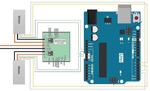
Here is the writing diagram. Note the only change is that we are powering both of the motor encoders from 5V per suggestion. Any ideas?

Nathan, I have found the solution. It’s the specific Dual MC33926 board I’m using. You answered a very similar question two years ago: Current sensing on dual MC33926 motor driver shield for Arduino: low values

I HIGHLY suggest that Pololu include this specific information in the spec sheet for that board and not just the chip itself; there a good chunk of researchers and hobbyists running these motors at low current draw and trying to use current sensing for control! Unless I missed it somewhere, but I did due diligence and read everything about the current sensing I could in the spec sheet for the board.

So I’m now at a crossroads. We’ve been grappling with trying to get experiments set for months now. We have the Arduino code perfected to work with that shield and library in particular and I am under a time crunch. I would prefer not to replace it with an entirely new shield and go through the fun of learning new libraries, specs, etc. You suggested this in that thread two years ago: https://www.pololu.com/category/118/current-sensors

My question is: could I directly integrate these with my current setup as is, a dual MC33926 stacked on top of an Arduino? I would like to continue using the MC33926 board for distributing power supply to the motors. From a quick read, it appears I can insert the sensors anywhere along the current path and they can be powered by the 3.3V Arduino Vout if I used the ACS711EX . This fits the motors running at 3-12V with almost certainly less than 1A of current. My plan at the moment (because my head is still swimming from the idea I might have to switch hardware) is to stack two of these on the free pins of the Arduino/33926 stack, but I’m unsure if I have the free pins to do it. I believe the output is analog, and therefore I could use the A2-5 pins which are not used by the motor shield. Or, and this is a bit more devious, could I snip the connections at A0 and A1 between arduino and motor board, route the hall effect sensor outputs to those Arduino pins, and use the native library functions with the more accurate current sensor?

Any insight you can offer regarding an inline current sensor such as this for my project would be immensely helpful. Again, Arduino Uno with dual MC33926, running a 14V input with 3-12V range on the HP12V 75:1 motors (due to speed variation), encoder readings, and a need to sense current to determine torque for mechanical power.

Or, I could perhaps use the ACS724(https://www.pololu.com/product/4041) because it has much better resolution, but requires 5v from the arduino. I thought the 5V output could handle two of these (max 14 mA) and the two motor encoders (10mA max) but it appears that 20mA is already pushing it.

What do you suggest I do? My instinct at this point is to search for the best possible resolution current sensor which can be powered by the 3.3V output for 3-12V and 0-2A range, because I’d prefer not to mess with adding any more hardware than I need to. Thanks for slogging through all of this.

The current sense of the MC33926 is typical of what you should expect from this kind of integrated feedback from an H-bridge; it is intended to give you a decent sense of what the driver is doing, and it is generally sufficient for coarse closed-loop current control and detecting problems like motor stalls or other conditions that might lead to damage or overheating. For precision current measurements, especially at low currents, you need a specialized sensors or measurement equipment.

Ultimately, for characterizing motors, I would suggest a setup where you power them directly from an adjustable power supply and measure those parameters you care about with precision meters. You can see a little more about how we characterize our motors in this post on our blog.

If you want to use our Hall effect current sensors, you would insert them anywhere in the current path between the driver and the motor, and you would connect the output to any free analog pin. You could disconnect A0 and A1 from the driver as you suggested, but that seems like unnecessary extra work given the code to read an analog voltage from the other analog inputs is not complicated (you can still use our library as a basis and just change the channel). By the way, it seems like you might be confusing the maximum current an Arduino Uno’s 5 V regulator can provide (approximately 800 mA) with the maximum current one of it’s I/O pins can provide (20 mA). Assuming you have things hooked up right, you should have enough 5V power for dozens of current sensors.

-Nathan

1 Like

Hey Nathan,

I just wanted to ask this question here since we’ve already gone through this thread. I’ll explicitly ask: we are trying to characterize the torque by using our measured current draw and the constant above. However, we’ve done no ground truth testing with any torque sensors to confirm the constant is indeed 0.022 on our particular motors. How much variation do you typically see on that constant with manufacturing of the motors? Is it something like a 5% variation? 10%? Or could the constant range be much wider?

For the record, we do not exceed 2A for the majority of the trials I am asking about.

You can get a rough idea of the variation by looking at the scatter of the data points in our performance graphs. The graphs are based on tests of five different motors, with five trials per motor, so there are 25 speed points and 25 current points at each load.

-Nathan