I have a few Arduino UNO micro-controllers, and 8 of the 2m RGB strips. I am attempting to run just the sample sketches that come with the PololuLedStrip library, but I am having no luck. I have the signal wire for the strip connected to pin 12, and the ground connected to GND. The LED strip is powered from a 5VDC 10A power supply. When running the sample program, I get no activity.
Showing this to a colleague, it was discovered that connecting the ground pin from signal connector on the LED strip to the signal connector on the UNO would light the correct number of LEDs on the strip, but not complete any of the sample color changes.
I have searched the forums here, and worn out my welcome with Google. I would like some advice from anyone with some experience with this setup. I’m currently checking to make sure the 5VDC 10A PS isn’t the issue.
This is the sample code I’m working with:
/* LedStripGradient: Example Arduino sketch that shows
 * how to control an Addressable RGB LED Strip from Pololu.
 *
 * To use this, you will need to plug an Addressable RGB LED
 * strip from Pololu into pin 12.  After uploading the sketch,
 * you should see a pattern on the LED strip that fades from
 * green to pink and also moves along the strip.
 */

#include <PololuLedStrip.h>

// Create an ledStrip object on pin 12.
PololuLedStrip<12> ledStrip;

// Create a buffer for holding 60 colors.  Takes 180 bytes.
#define LED_COUNT 60
rgb_color colors[LED_COUNT];

void setup()
{
}

void loop()
{
  // Update the colors.
  byte time = millis() >> 2;
  for(byte i = 0; i < LED_COUNT; i++)
  {
    byte x = time - 8*i;
    colors[i] = (rgb_color){ x, 255 - x, x };
  }

  // Write the colors to the LED strip.
  ledStrip.write(colors, LED_COUNT);

  delay(10);
}
As an update to this, I was able to get a little control by running the ground from the data circuit back through an input with the pull-up resistor enabled. However, behavior is still ‘inconsistent’. The first LED on the strip seems to be inaccessible, as the entire array seems to be shifted by one. The RGB values that I would expect (i.e. 255,0,0 for RED) are opposite (i.e. 0,255,255 for RED).
I’m wondering if it was a mistake going with this method of signal vs. a PWM offering that I have seen.
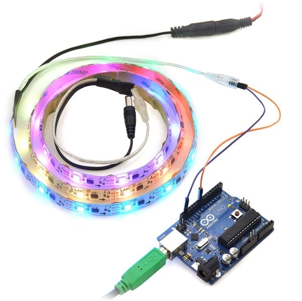
It is not clear to me how your system is set up, but the ground wire from the LED strip should be connected to the ground pin of your Arduino. Could you provide more detail about your setup (maybe include a picture)? It should be as simple as connecting the signal and ground wires from the LED strip to the Arduino, as shown in the picture below:
If you had your ground pin connected to something other than the Arduino’s ground, you might have damaged the strip.
Also, I’m not sure how many LED strips and Arduino Unos you are using, but you should simplify your setup by using just one Arduino Uno to control one LED strip until it works properly.
I am currently configured with the power to the strip being provided via an external 5VDC 10A brick power supply. The connections for the singal connector are connected to: Pin 12 for signal, and Pin 7 for ground connection. Pin 7 is running a pinMode of INPUT_PULLUP. I tried several other combinations with no success.
I attempted the configuration (using the recommended pin 12 instead of the pin 8 in the picture) you are referring to with a new UNO and a new strip. It did not function. Except for the first LED (and the backwards colors), the system seems to work very well in the current configuration. The irony is that the first LED on the second strip behaves correctly. However, if I swap the strips, it is always the first LED on the first strip that has an odd behavior. This would tend to show that it is not a damaged strip.
If I run the UNO on any other supply outside of the USB connection on the PC, I have to tie the UNO’s ground to earth ground in order to get it to function.
The LED strip shows a VDC input range of 5V-12V. Is this an acceptable range? I ask because it would be convenient to run the UNO (7-12VDC) off the same power supply as the strip.
Why are you connecting your strip’s ground pin to an input? The ground wire from the signal connector should be connected to the pin labeled GND on the Arduino (the whole point is for your strip and Arduino to have a good common ground).
The LED strips run on 5V, but you could power the Arduino Uno from the same power supply using a boost regulator like this one.
Also, how many LED strips are you connecting in series? From a power perspective, your chained strips must not exceed 5m in length, though it is fine for the signal chain to be as long as you want.
I tried that configuration first, and several times during my troubleshooting process. I am connected to an input to use the internal pull-up resistor because it is the only way the LED strip would function. This was based on the possibility of signal reflection on the line, using the input was the easiest way to test this. It completes the circuit as required, but provides some resistance to eliminate any reflection. I could have accomplished the same thing by putting a resistor between the GND pin and the GND contact, but I did not have a resistor of sufficient resistance on hand. This was not just me looking at this. I had several EEs looking at it as well.
Please understand that I did attempt the configuration described here (https://www.pololu.com/catalog/product/2541). I tried this with multiple 2m strips, and multiple Arduino controllers. Putting the pull-up resistor into the circuit was somewhere around attempt 25-30 to get this to function. The behavior is consistent in any combination of hardware I try with the resistor. I get no activity when connected directly to ground.
I have tried different power supplies to the Arduino. I have tried different power supplies to the led strip. I have tried different output pins on the Arduino. I have tried different Arduino controllers (UNO R3). I have tried different grounds. I have tried different sketches.
Do you have any additional troubleshooting options to see why this is? I would prefer to make some progress on this, or at least understand why this is happening. Tell me to connect the signal ground wire to GND again isn’t going to make it function. I like the quality of the LED hardware and I would really like to stay with it. I can function with the current configuration if needed, but obviously I would have liked to hook it up as described.
I’m perfectly willing to pull a new strip out of the sealed packaging, and new Arduino out of the box and try it again.
The goal is to connect two 2m strips in series per Arduino controller. This is a operator pacing application intended to give a guide for speed of an operation. The Arduino is currently connected to a 2A 9VDC supply, and the LED strip(s) are connected to a 10A 5VDC supply.
My boost supply is arriving today. Thank you for that suggestion.
The information provided in this post https://forum.pololu.com/t/additional-chassis-level/41/1 corrected my issue. It was nice to know that someone else had the same issue, and that it wasn’t a wiring issue. Unfortunately, I had already purchased some pwm based strips to meet my deadline as a prototype device. The customer prefers the quality and shape of the Pololu strip, and I returned to see if I could get them working.
Now that I have returned to these, and I am able to control the strip appropriately, I’m running into timing issues. My sketch is time based, using the milliseconds from the start of the cycle as a timer. While this works with the pwm based strip, the process of writing to the strip seems to actually slow down the internal clock. A process that should take 10 seconds will take close to a a minute. If I take out the comment out the .write commands, the clock goes right back to normal. Is this expected? Is there a way around this? This project requires the internal clock to be accurate.
I am sorry you had trouble with the LED strips. You should be able to use version 2.0.0 of the PololuLedStrip Arduino library with your strips without modifying it.
While colors are being sent to the LED strip, we have to disable interrupts to ensure the right colors are sent. This means that the Arduino environment’s timer interrupt for keeping time will be delayed. If the timer interrupt happens multiple times while the interrupts are off, only one interrupt will actually be recorded, and this results in the system time appearing to run slowly.
We got around this problem in our demo code by adding a 10 ms delay to the main loop. This ensures that the Arduino spends only a minority of its time sending colors. I suspect you don’t have any delay like that, and if you added the delay then your 10-second process would take much less than a minute to run. That might be good enough.
If that is not good enough for you, you could try using the interruptFriendly option of the library, which is documented on the page I linked to above. However, in our experience the Arduino’s timer ISR takes too long so it causes an unwanted reset signal to be sent to the LED strip, resulting in bad flickering. The Arduino IDE is open source though, so you might be able to rewrite the ISR in assembly and make sure it never takes longer than about 8 microseconds. You can probably just edit a .cpp file somewhere in the Arduino directory to make that happen.
Another option is to keep track of your own time by just having a variable that you increment every time your main loop runs. Sending colors to the LED strip takes a predictable amount of time, and maybe the rest of your main loop is predictable too.