I have questions regarding Arduino Uno A4 A5 pins for using Zumo Robo V1.2.
My system has SPI whose pins could not be moved and completely collided with the Zumo Robo’s pins. Then, I switched several pins (6 or more) with changing pin # in library files. Then I found a problem.
Q1: Is it possible to use A4 or A5 pins for sensor pins after being compass jumper unconnected (cut) ?
I found problem, as shown below.
Q2: Without any trouble, I used A4 for DIR-R and A5 for Zumobotton for Linefollower.ino.
As far as my experience, I have found no problem.
Can A4 and/or A5 pins be used for digital pins without compass jumper unconnecte (cut) ?
<<< Q1: LineSensorTest >>>
I used LineSensorTest.ino for test in the latest Example folder of the Zumo shield. #11pin for Zumo is connected A4 pins for Arduino using Jumper wire.
unsigned char sensorPins = { 4, A3, 11, A0, A2, 5 }; ← default
unsigned char sensorPins = { 4, A3, A4, A0, A2, 5 }; ← changed
result for Line sensor test (serial monitor)
4 A3 A4 A0 A2 5
2000 2000 2000 2000 2000 2000 E <—lift up Zumo
2000 1916 2000 1880 2000 2000 E
1500 1212 2000 1136 1252 2000 E <— lift down on the white paper
1508 1180 2000 1060 1140 1764 E
1348 1104 2000 944 1020 1556 E
1348 1064 2000 944 1024 1516 E
1308 1064 2000 944 1024 1516 E
1308 1060 2000 940 1020 1516 E
1348 1060 2000 940 1020 1556 E
1348 1060 2000 940 1020 1556 E
1308 1060 2000 940 1020 1516 E
1308 1060 2000 940 1020 1516 E
1308 1060 2000 940 1020 1516 E
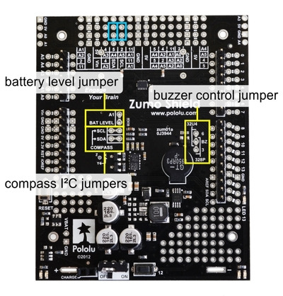
If you want to use pins A4 and A5 on your Arduino Uno for something other than connecting to I2C devices, then you should cut the thin traces between the pairs of holes labeled “compas I2C jumpers” in the picture below.
Can you clarify if you did that before seeing the output you posted? If you had cut the trace, can you confirm that you broke the connection by measuring the resistance between the pins while your Zumo is unpowered?
I cut both of SDA and SCL before setting the system. Now I checked the resistances "over the load” while the Zumo is unpowered, again.
I try to find root cause in my system other than Zumo or Arduino.
This is a public forum, so I edited your post to remove the contact information.
I am not sure what you are saying about the resistances. Can you clarify what your multimeter measured? Also, can you post some pictures of your Zumo that show all of the connections that you cut as well as all of the connections you added?
The resistances is an order of M ohms more.
I checked that your Zumo moves perfectly after cutting connection.
Finally, I found our additional board has I2C Bus (not used, pulled up), which has pins compatible those of arduino.
(Zumo-Grove base shield-Our board- Arduino Uno)
Our board(w/ SPI) is an accelerator for controlling Zumo move, through Arduino.
Finally I found I can use 2 or 3? (at least w/ zumo 6 IR sensors) pins for other purposes.
Sorry bother you so often. Now system is working very well.
Best regards, Hiroshi
2022/07/07 3:18、Patrick via Pololu Forum <inbox@pololu.com>のメール:
This is a public forum, so I edited your post to remove the contact information.
I am not sure what you are saying about the resistances. Can you clarify what your multimeter measured? Also, can you post some pictures of your Zumo that show all of the connections that you cut as well as all of the connections you added?