
Awesome! I’ll test\add those when I get home.
I’ve added the jumper wire and the servos are powered by a 6v rc battery pack currently showing 5.5v while the Pololu board is powered. The yellow light stays on solid even if the only thing connected is the battery pack. The servo jumps when power is turned on.
Any ideas why the yellow led is on?
Phil
My graphics aren’t totally clear about this (I only made them to illustrate the possible power connections), but I have a guess. You should disconnect the Arduino bus power line from your servo controller if you’re going to power it from the servo battery, which I’m guessing you did, but you still need the serial wire and a ground wire connection between the Arduino and the servo controller. Did you perchance disconnect both wires?
-Adam
Ahhh…I did disconnect the ground wire. I’m charging up the battery pack and will try it again WITH the ground wire connected.
Thanks,
Phil
IT’S ALIVE!
Thanks for your help an patience as I made every rookie mistake without frying the board. Now I have multiple servos moving and can begin working on servo routines.
Thanks again,
Phil
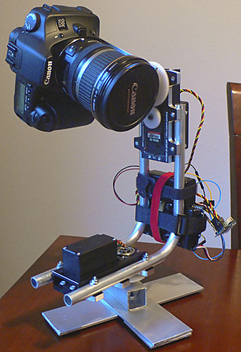
Here’s where the Pololu servo controller has been put to work for now. It will be a week or two until I have the 360 panobot ground version completed.
Thanks for you help,
Phil
Looks very nice, I’d love to see more, like maybe a video when it’s all done.
-Adam
Adam,
Here’s a video of the Pololu micro servo controller board at work. phil007.com/panobot/
I’m trying to adjust the servo speed but the code I entered from above isn’t working for me…what did I do wrong this time! The code below is what I’m using to test the servo speed. The servos continue to run at full speed.
Thanks,
Phil
int panServo;
int tiltServo;
int panDelay = 4500;
int tiltDelay =5000;

void setup()// run once, when the sketch starts
{
  Serial.begin(9600);
}

void loop() //Main program loop, executes forever after setup()
{

  servoSetSpeed(0,10);   // Pan servo speed
  put(0,5000);           // Pan servo right
  delay(panDelay);       // Delay

  servoSetSpeed(0,50);   // Pan servo speed
  put(0,4000);           // Pan servo right
  delay(panDelay);       // Delay

  servoSetSpeed(0,100);  // Pan servo speed
  put(0,3000);           // Pan servo right
  delay(panDelay);       // Delay

  servoSetSpeed(0,127);  // Pan servo speed
  put(0,2000);           // Pan servo right
  delay(panDelay);       // Delay

  servoSetSpeed(0,127);   // Pan servo speed
  put(0,5000);           // Pan servo right
  delay(panDelay);       // Delay

  delay(10000);          // 10 second delay

}

void put(int servo, int angle)
{
  //servo is the servo number (typically 0-7)
  //angle is the absolute position from 500 to 5500

  unsigned char buff[6];

  unsigned int temp;
  unsigned char pos_hi,pos_low;

  //Convert the angle data into two 7-bit bytes
  temp=angle&0x1f80;
  pos_hi=temp>>7;
  pos_low=angle & 0x7f;

  //Construct a Pololu Protocol command sentence
  buff[0]=0x80; //start byte
  buff[1]=0x01; //device id
  buff[2]=0x04; //command number
  buff[3]=servo; //servo number
  buff[4]=pos_hi; //data1
  buff[5]=pos_low; //data2

  //Send the command to the servo controller
  for(int i=0;i<6;i++){
    Serial.print(buff[i],BYTE);
  }

}

void servoSetSpeed(int servo, int speed){
   //servo is the servo number (typically 0-7)
   //speed is servo speed (1=fastest, 127=slowest)
   //set speed to zero to turn off speed limiting

   unsigned char buff[5];
   unsigned char speedcmd;

   speedcmd=speed&0x7f;//take only lower 7 bits of speed

   buff[0]=0x80;//start byte
   buff[1]=0x01;//device id
   buff[2]=0x01;//command number
   buff[3]=servo;//servo number
   buff[4]=speed;//data1

   for(int i=0;i<5;i++){
      Serial.print(buff[i],BYTE);
   }
} Super-cool panorama Phil! I bet a lot of people would be interested in your project just as a way to make such nice panoramas with an ordinary camera. What software did you use to do the stitching?
Anyway, as I said, I rewrite these functions from some Windows code I wrote, and I didn’t actually test my speed function on an Arduino (or otherwise, for which there is no excuse!), and while it does technically work as written, there are a couple of minor things wrong with it.
First off, I do have the speed settings backwards in my comments. 0 is no speed limiting, but 1 is the slowest possible servo motion, with 127 being the fastest. Something to keep in mind is that most servos won’t be able to keep up with the faster speeds anyway. I’m testing this on an old junker Hobbico servo, and it maxes out at about 45, so any setting above 45 just moves at the servo’s max speed.
You’re using those Servo City down-gearing boxes, so your max speed is going to be even lower than with just the servo alone. Maybe in the 1-10 range. Now, you thought you were using the slowest speed, but the last command in your test code loop ends by putting the servo back to 5000 at speed 127, the fastest limited speed possible. When the loop repeats, your first command drives the servo to 5000 at speed 10, which you might actually be able to see, but the servo is already at position 5000 so it doesn’t go anywhere!
I also do a check to clear the highest bit of the input number, just in case you try to put in like 255 or something, but the code as written doesn’t actually use that new variable! Come to think of it, I have a lot of variables declared as integers, when they really only need to be characters, and sending the commands byte by byte the buffers are really unnecessary (It made much more sense to write it this way in Windows). Also, I’m compiling this in Arduino for the first time, and “speed” seems to be some sort of reserved variable name (it turns maroon in the editor). I don’t know what it does, and while it seems to work, I should name it something else just to be on the safe side.
So, the Arduino-safe (and now tested!), and less memory hogging servo control functions would look like this:
void put(unsigned char servo, unsigned int angle){
	//servo is the servo number (typically 0-7)
	//angle is the absolute position from 500 to 5500

	//Send a Pololu Protocol command
	Serial.print(0x80,BYTE); //start byte
	Serial.print(0x01,BYTE); //device id
	Serial.print(0x04,BYTE); //command number
	Serial.print(servo,BYTE); //servo number
	//Convert the angle data into two 7-bit bytes
	Serial.print(((angle>>7)&0x3f),BYTE); //data1
	Serial.print((angle&0x7f),BYTE); //data2
}

void servoOff(unsigned char servo){//turns off a servo
	//(servo will go limp until next position command)
	//servo is the servo number (typically 0-7)

	//Send a Pololu Protocol command
	Serial.print(0x80,BYTE);//start byte
	Serial.print(0x01,BYTE);//device id
	Serial.print(0x00,BYTE);//command number
	Serial.print(servo,BYTE);//servo number
	Serial.print(0x0f,BYTE);//data1 (turn servo off, keep full range)
}

void servoSetSpeed(unsigned char servo, unsigned char speedcmd){
	//servo is the servo number (typically 0-7)
	//speed is servo speed (1=slowest, 127=fastest)
	//set speed to zero to turn off speed limiting

	speedcmd=speedcmd&0x7f;//take only lower 7 bits of the speed

	//Send a Pololu Protocol command
	Serial.print(0x80,BYTE);//start byte
	Serial.print(0x01,BYTE);//device id
	Serial.print(0x01,BYTE);//command number
	Serial.print(servo,BYTE);//servo number
	Serial.print(speedcmd,BYTE);//data1
}
I hope Zagrophyte is still watching this thread!
-Adam
P.S. Aptly named, and intentionally or not, Arduino is Italian, and translates as “a little arduous.” Only a little! Actually I’m not sure that it’s proper to apply the -ino suffix to an adjective, like arduo, but it is funny!
Adam,
Thanks again for you quick support. I now have full control over the servo speed.
I used PTGui to stitch the pictures. When I get a little better with stitching the program I’ll fix the errors.
In a few weeks when I get code fine tuned I’ll post a “how to” on building this panobot that will include part sources and code.
Phil
Hello,
I was wondering when we would see your “How To” break down for building the Panobot. I am really interested. I also wanted to know what the black box underneath the Arduino was for.
Thanks
DIY parts list is coming soon, maybe this weekend. The basic code from this tread will get you taking pictures. It could be a month or two until I have anything better.
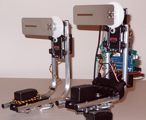
Number two was completed today.
Phil
Thanks. I will be patiently waiting for the DIY list.
By the way, are you planning on selling these? How much?
It’s a DYI project, Do It Yourself. 
Here’s picture of all the parts I used to build my panobot. After clicking on the image you’ll see notes that include descriptions and links.
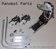
Who’s going to build the next one? ![]()
Phil
Phil,
Thanks so much for the equipment breakdown. You are very generous with your knowledge. I am hoping to build this pretty soon. I currently have the Canon A640 with Canon wide angle lens and adapter. I guess I am gonna have to program the Arduino Diecimila to take a lot more pictures for the spherical pano.
By the way, would it be to much to ask for a wiring diagram. I really would like to know where all the wires go.
Thanks again for your help
Thought I’d chyme in and point out that, although they are awesome and everyone should have one to play with, you don’t actually need a microcontroller (i.e. the Arduino) to command the Pololu serial servo controllers. For example, The Micro Serial Servo Controller has an RS-232 level serial input, so you could cut up a serial cable and command it directly from a computer. You could also use a USB to Serial adapter (RS-232 or TTL level, the only difference is where you make your connections).
There are advantages to doing it either way, just thought you might like to know.
-Adam
For a while now I thought that the Vcc=Vs jumper on the Pololu serial servo controllers connected the servo power to the on-board voltage regulator, so in this case the servo power had to be greater than five volts.
It turns out (thanks Ben!) that this jumper actually bypasses the on-board regulator, and applies the servo power voltage directly to the on-board PIC microcontroller! So, if you’re using one source for both servo and electronics power through the Vcc=Vs jumper, it needs to be less than 5V, not more.
Fortunately for me (and maybe you too) the absolute maximum voltage rating on the PIC16F628A is 6.5v, or none of my servo controllers would be working right now!
So, the correct power options for the serial servo controllers are:

I went through and edited the wrong values wherever I could find them, but I thought I should also add a new post about it to this thread. Sorry about the mix-up!
-Adam
Thanks for the info!!
Hmmm…I’ve been using a 6 cell battery pack like this one and it’s reading 6.65v after some use. I’m sure the voltage reads higher when it comes off the charger.
Now might be a good time to try out the 5 cell pack. 
Phil