Ardiuno UNO and a4983 with regulator and stepper motor

Have you soldered your the header pins to the stepper driver board yet? There is no reason to expect anything to work with unsoldered pins, so it’s not worth trying to help you debug your system while there is still such a glaring problem. By the way, there really isn’t any down side to soldering first (soldering header pins does not commit you to any particular connections).

- Ben

Point well taken Ben.

So please excuse my lack of knowledge here

The header pins are the strips of pins encased in plastic correct?
And do I only use/solder the amount of header pins that are being used on the chip?
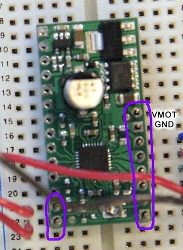
2 on the bottom left and 8 on the right?

Or shold I just solder them all, incase I need to use more pins later?

Please advise, thanks.

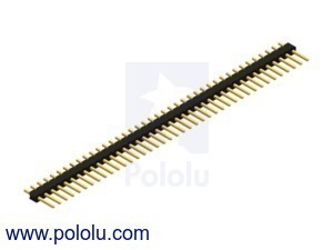
Yes, the header pins look like this:

The short sides of the pins protrude through the through-holes on the board (like in the picture you posted earlier) and should be soldered to the surrounding pads on the top side of the PCB if you want to be able to plug it into a breadboard. If you do not have much soldering experience, I strongly suggest you find a tutorial on soldering and familiarize yourself with it before you start so you know how to apply the solder, how much solder to add, what a good solder joint looks like, etc. Otherwise, you might damage the board or create bad solder joints that don’t make adequate electrical connections.

Specifically, you should at least solder the places circled in the picture below:


I recommend you solder header pins in all the holes while you’re at it, but this isn’t absolutely necessary. The crucial part is soldering the pins you are using to the board. If you solder all the pins, it makes it easier to make alternate connections later (i.e. you won’t have to go looking for soldering iron again).

Also, this might sound obvious, but just in case it isn’t: you should not solder the board while power is being applied. In general, make sure you are really paranoid about applying power with incorrect connections as putting the wrong voltages on pins or shorting outputs together can permanently destroy electronics.

- Ben

Ben this is exactly the information i was looking for - thanks so much!

I’ll get soldering tonight after ive had a bunch of beer and put my tinfoil gloves on :wink: Jokes

I am super paranoid about messing this up, hence all my questions.

Thanks again.
Ill get on this either tonight or tomorrow and get back to you.

Ok guys, working so-so here

The Stepper Motor, rotates about a1/4 the way around > pauses for 1 second > repeats

Variation i just did was to comment out the delay, and set the speed to (1)

Next step (no pun) How would I wire and code the Potentiometer?

With following Sketch

// Stepper
#include <Stepper.h>

// steps value is 360 / degree angle of motor
#define STEPS 200

// create a object on pins 6 and 7
Stepper stepper(STEPS, 6,7);

void setup()
{
}
void loop()
{
///// Turn the stepper 200 steps with a 1 sec delay between steps at 60rpm
/// then reverse the direction and do 50 steps at 20rpm with a 1sec delay between steps
stepper.setSpeed(1);
stepper.step(200);
//delay(1000);
//stepper.setSpeed(20);
//stepper.step(-50);
//delay(1000);
}

It looks like you are still using the stepper library that I mentioned has little chance of working. Can you confirm that this is the stepper library you are using? http://www.arduino.cc/en/Tutorial/Stepper I looked at the code for this stepper library and confirmed that it will not work with our driver.

For the potentiometer, you would connect two ends of the pot between 5V and GND of your Arduino and then connect the wiper to one of the Arduino’s analog inputs. Then you can use analogRead to read the wiper voltage. Feel free to post your circuit before you power it.

- Ryan

Hi there, yes that is the Stepper Library I am using.

So are you saying that, with that library, the POT wont work? Currently with that library installed I am able to control the Steps and RPM of the motor.
Should I comment that include line out?

Here is my illustration for the POT wiring - will it be ok to run the wire from the POT to the same 5V pin on the Arduino as the Driver board?
I dont see anywhere else to ruin it too

I just noticed that my Stepper Motor was extremely HOT to the touch

I am using a 12v 3.6Ah/C20 Lead Acid battery

I then plugged in a regular off the shelf 9v battery, ran the sketch and the Motor gave off a high pitched squeal - but still ran fine.

Should I be concerned with this?

The motor I am using is
Stepper Motor: Unipolar/Bipolar, 200 Steps/Rev, 42x48mm, 4V, 1200mA

Here is a zoomed area of the POT wired to the Breadboard for your review.

No, it has nothing to do with the pot. That stepper motor driver library is designed to work with systems where the two wires control which coils are currently energized. Your two wire interface is step and direction. That it is working at all is pretty much just a coincidence.

I recommend you use the simple sketch Ben and I suggested earlier in this thread and stop using that library. Does your stepper motor still get hot after using the other code?

Assuming you are right about which pin the wiper is on your pot, your potentiometer wiring looks correct.

- Ryan

Thanks again Ryan, im not sure about the heat of the Motor untill do the below:

SO before I upload the code
KNowing that I am using pins 6, and 7 on the Arduino, And Step and Dir on the a4398. How do i modify the Sketch and the wiring to run the below skecth? (specifically the enable pin???)

#define stepPin 2
#define dirPin 3
#define enablePin 4
void setup()
{
// We set the enable pin to be an output
pinMode(enablePin, OUTPUT);
// then we set it HIGH so that the board is disabled until we
// get into a known state.
digitalWrite(enablePin, HIGH);
Serial.begin(9600);
Serial.println("Starting stepper exerciser.");
pinMode(stepPin, OUTPUT);
pinMode(dirPin, OUTPUT);
}
void loop()
{
int j;
// set the enablePin low so that we can now use our stepper driver.
digitalWrite(enablePin, LOW);
// wait a few microseconds for the enable to take effect
// (That isn't in the spec sheet I just added it for sanity.)
delayMicroseconds(2);
// we set the direction pin in an arbitrary direction.
digitalWrite(dirPin, HIGH);
for(j=0; j<=10000; j++) {
digitalWrite(stepPin, LOW);
delayMicroseconds(2);
digitalWrite(stepPin, HIGH);
delayMicroseconds(1000);
}}

You already modified the code to work with your setup. Have you tried it since you did the soldering?

- Ryan

Youre right, i did - my bad.

Ok all wired and soldered here, everything is working fine
I just couldnt find the EN pin on the a4983, but did.

Now for the POT.

I have wired just like my last graphic shows (the zoomed version).

I am currently running

#define stepPin 7
#define dirPin 6
#define enablePin 5
void setup()
{
  // We set the enable pin to be an output
  pinMode(enablePin, OUTPUT);
  // then we set it HIGH so that the board is disabled until we
  // get into a known state.
  digitalWrite(enablePin, HIGH);
  Serial.begin(9600);
  Serial.println("Starting stepper exerciser.");
  pinMode(stepPin, OUTPUT);
  pinMode(dirPin, OUTPUT);
}
void loop()
{
  int j;
  // set the enablePin low so that we can now use our stepper driver.
  digitalWrite(enablePin, LOW);
  // wait a few microseconds for the enable to take effect
  // (That isn't in the spec sheet I just added it for sanity.)
  delayMicroseconds(2);
  // we set the direction pin in an arbitrary direction.
  digitalWrite(dirPin, HIGH);
  for(j=0; j<=10000; j++) {
    digitalWrite(stepPin, LOW);
    delayMicroseconds(2);
    digitalWrite(stepPin, HIGH);
    delayMicroseconds(1000);
  }
}

Whats next? The Pot Sketch?

BTW Motor is starting to heat up, slowly using the above sketch - is assume that is normal? Driver board is not warming up, which I assume is good.

I got this work - but it confuses me that it is defining 4 pins and I am only using 3.
I using pins 5, 6, 7, on the Arduino
to
Pins
DIR , Step and EN on the a4398

Is this why it won’t change direction, and the motor gets hot again?

    //This example demonstates the use of the ULN2003 to drive a stepper motor.
    //The speed and direction of the stepper motor is determined by adjusting
    //the potentiometer connected to A2. When the potentiometer is [code]rotated fully
    //counterclockwise, the motor will rotate at full counterclockwise speed. As
    //the potentiometer is rotated clockwise, the motor will continue to slow down
    //until is reaches its minimum speed (when the potentiometer is at the middle
    //position.) Once the potentiometer crosses the middle position, the motor will
    //reverse direction. As the potentiomer is rotated further clockwise, the speed
    //of the motor will increase until it reaches its full clockwise rotation speed
    //when the potentiometer has been rotated fully clockwise.

    //////////////////////////////
    ////////////////////////////////////////////////
    // SOURCE
    
    //http://www.expertcore.org/viewtopic.php?f=92&t=2529    
    
    //declare variables for the motor pins


    int motorPin4 = 5;
    int motorPin3 = 6;
    int motorPin2 = 7;
    int motorPin1 = 8;

    int motorSpeed = 0; //variable to set stepper speed
    int potPin = 0; //potentiometer connected to A2
    int potValue = 0; //variable to read A0 input

    //////////////////////////////////////////////////////////////////////////////
    void setup() {
    //declare the motor pins as outputs
    //int potValue = potValue*2;
    pinMode(motorPin1, OUTPUT);
    pinMode(motorPin2, OUTPUT);
    pinMode(motorPin3, OUTPUT);
    pinMode(motorPin4, OUTPUT);
    Serial.begin(9600);
    }

    //////////////////////////////////////////////////////////////////////////////
    void loop(){

    potValue = analogRead(potPin); //read the value of the potentiometer
    Serial.println(potValue);//View full range from 0 - 1023 in Serial Monitor
    if (potValue < 511){ //if potentiometer reads 0 to 511 do this
    motorSpeed = (potValue/15 + 8); //scale potValue to be useful for motor
    clockwise(); //go to the ccw rotation function
    }
    else { //value of the potentiometer is 511 - 1023
    motorSpeed = ((1023-potValue)/15 + 8); //scale potValue for motor speed
    counterclockwise(); //go the the cw rotation function
    }
    }

    //////////////////////////////////////////////////////////////////////////////
    //set pins to ULN2003 high in sequence from 1 to 4
    //delay "motorSpeed" between each pin setting (to determine speed)

    void counterclockwise (){
    digitalWrite(motorPin1, HIGH);
    digitalWrite(motorPin2, LOW);
    digitalWrite(motorPin3, LOW);
    digitalWrite(motorPin4, LOW);
    delay(motorSpeed);
    digitalWrite(motorPin1, LOW);
    digitalWrite(motorPin2, HIGH);
    digitalWrite(motorPin3, LOW);
    digitalWrite(motorPin4, LOW);
    delay (motorSpeed);
    digitalWrite(motorPin1, LOW);
    digitalWrite(motorPin2, LOW);
    digitalWrite(motorPin3, HIGH);
    digitalWrite(motorPin4, LOW);
    delay(motorSpeed);
    digitalWrite(motorPin1, LOW);
    digitalWrite(motorPin2, LOW);
    digitalWrite(motorPin3, LOW);
    digitalWrite(motorPin4, HIGH);
    delay(motorSpeed);
    }

    //////////////////////////////////////////////////////////////////////////////
    //set pins to ULN2003 high in sequence from 4 to 1
    //delay "motorSpeed" between each pin setting (to determine speed)

    void clockwise(){
    digitalWrite(motorPin4, HIGH);
    digitalWrite(motorPin3, LOW);
    digitalWrite(motorPin2, LOW);
    digitalWrite(motorPin1, LOW);
    delay(motorSpeed);
    digitalWrite(motorPin4, LOW);
    digitalWrite(motorPin3, HIGH);
    digitalWrite(motorPin2, LOW);
    digitalWrite(motorPin1, LOW);
    delay (motorSpeed);
    digitalWrite(motorPin4, LOW);
    digitalWrite(motorPin3, LOW);
    digitalWrite(motorPin2, HIGH);
    digitalWrite(motorPin1, LOW);
    delay(motorSpeed);
    digitalWrite(motorPin4, LOW);
    digitalWrite(motorPin3, LOW);
    digitalWrite(motorPin2, LOW);
    digitalWrite(motorPin1, HIGH);
    delay(motorSpeed);
    }

You have got to stop randomly using code for other products and hoping that they will somehow magically work with your particular driver! This comment should be a huge red flag that you’re doing something wrong:

//This example demonstates the use of the ULN2003 to drive a stepper motor

This kind of engineering approach almost ensures you will destroy something.

- Ben

Point well taken Ben, thanks - I tend to get a little ahead of myself sometimes.

So what do you suggest, that would be proper to use (and safe) to adjust the stepper speed with a POT?

I think as a first step you should make sure that you have code that controls the stepper motor properly at a speed you can set by changing a variable in your code. Next, I would write a program that reads a potentiometer value and maybe prints it to the serial monitor. Once you have those two working separately, you can take the next step and try to combine them (and we can potentially help you).

- Ben

That is my game plan exactly.

The Stepper Test code works perfectly, I just need to figure out how to adust the speed.

What would be ideal is this Micro Stepping ive been reading about. Do you know of a edited version of that sketch, with number of steps defined and speed? - variable to control

What is Micro Stepping? Is that possible with my configuration?

I really apprecaite the awesome help so far!
Thank you so much