APA120c versus WS2812b

We are busy to design a string of lights in buildings with single LED’s, but controlled with a u-processor. Probably an ATtiny861a (or equal). The LED’s, mounted at the PCB-strip like <0.5 meters, 72 LEDs>, will be cut in seperate LED’s and will have wires from a connector-block to the LED’s in serial connection. Each building will have from 1 upto 8 LED’s and probably one string will hav upto 30 buildings (so the maximum will be 240 LED’s in one string).

Do we need special attention in the wiring for the strings for these LED’s?
Power-supply will be done at every x buildings seperatly. The data-string will be one string, of course.
Do we need capacitors in the chain for the power-supply, like 100nF ?
What is the maximum length of the data-bus?

And in a later stadium the lightning of the layout.
Is there only the RGB-LED’s with the build-in controller?
We want to combine RGB-strips with White (warm and cold) to have enough ligth at the layout and the oppertunity to play with the color of the light like the real sky. In the night only the blue color and in the morning and evening a bit red while in daytime clear white.

So which of the LED’s do you recommend?
Is it the WS2812b?
or the APS102c?

with regards,
Willie de Kort
the Netherlands,
www.mbvdewissel.com (unfortunatly only in Dutch)

Hello, Willie.

The order in which you wire the LEDs determines how they will react to your code. Your plan to power the strings of LEDs separately sounds like a good way to go. Each LED segment essentially acts as a buffer for the data line, so it can be as long as you want (as long as there is not a long enough wire between LEDs that could result in significant losses). At very long lengths you might start noticing delays between when the first and last LED updates. The addressable LED strips we currently carry all use RGB LEDs. You might be able to fake a warm and cold white using the RGB values though.

As far as adding capacitors to the power rail, it would probably depend on which LED strip you use. For example, when using the WS2812B-based LED strips, we recommend taking a few precautions, such as adding a capacitor on the power rail, adding a 100 to 500 ohm resistor between your microcontroller’s data output and the LED strip to reduce the noise on that line, and minimizing lengths of the wires connecting your microcontroller to the LED strip. So far, we have not seen the need for adding capacitors to the APA102C-based LED strips.

Ultimately, both types of LED strips would probably work for your application, but we generally consider the APA102C-based strips to be less sensitive than the WS2812B ones. They also offer a few extra features as well, such as being able to adjust the brightness separately from the RGB color values, and they use a much higher PWM frequency for controlling each color channel, making them less prone to flickering when recorded. A more detailed comparison can be found on the product pages for either type of strip.

-Brandon

Hi Brandon,

Thanks for the reply, it sound as it would be possible to use these kind of LED’s.
I think the APA102c will be the best choise, because the ‘bus’ is not the same in length between the LED’s and this will influence the timing of the signals.

A new question I do have :confused:
What will happen to the LED’s when they are wrong connected to VCC/GND/Di/Ci?

All the buildings will be removed/placed on the layout during years of construction. And when a part of the layout will be finished 1 or 2 building will be removed/replaced for maintenance. The LED’s will be positioned in the buildings (every building 1~8 LED’s) and connected by small connectors. The lights will be switched on/off according time of the day … livingroom, bedroom, etc.


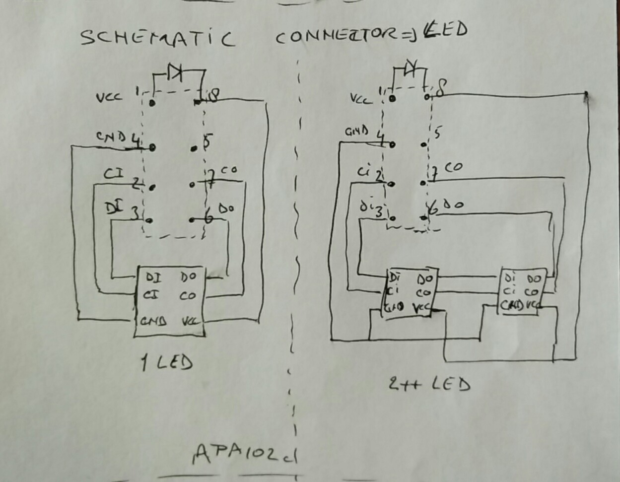
To make this possible, we want to make a small PCB - with a 2x4 connector - below the layout-board and wire the LED’s to the opposite-connector. The type will be like https://www.pololu.com/product/1024 and a part of https://www.pololu.com/product/966.


With these type of connectors it is (of course) possible to position them wrong to each other… :confused: :cry:
It is possible to shift the positions or rotate them over 180 degrees and shift them as well…

I can and will protect the VCC powersupply for the LED-string in every building with a diode.

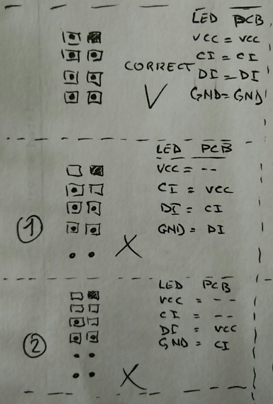
The first option I have is a ‘coded’ connector-set, 1 male-pin cut away and 1 female-hole blocked. But that will only be a part of the solution, shifting is still possible. And it is possible to connect VCC/GND to Di,Ci of the LED’s. See the attachments.

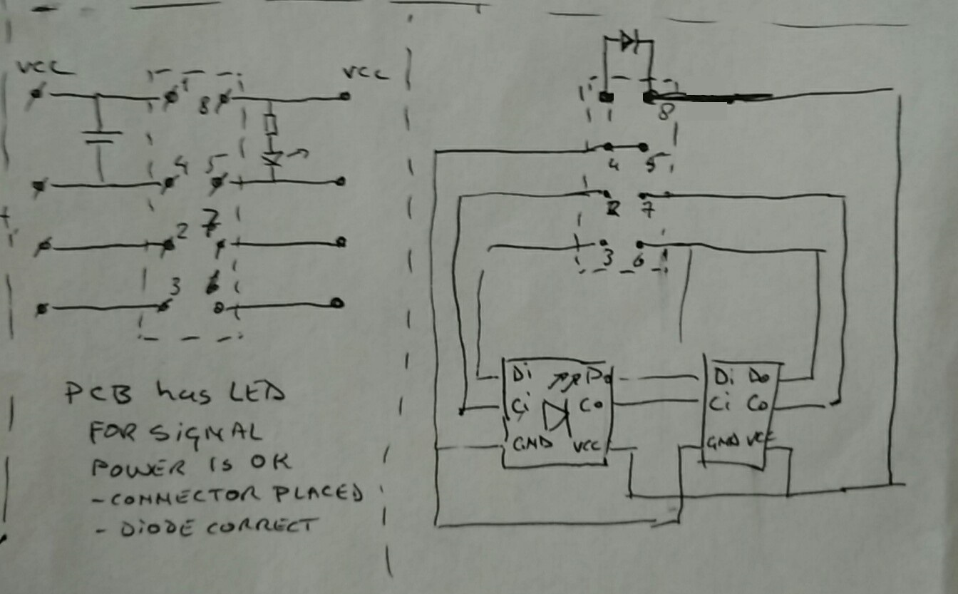
The second option is a PCB with a small LED to show the correct position of the connector, VCC and GND are correct connected by the male-header,
the LED is on (visual check) or opto-coupler will signal correct position to the controller (which will start the data).


So what is the risk for the LED’s when they are wrong connected?
What will happen?

For APA102c:
Case 1/2 - connector shifted ‘up’:
=> LED’s wire

  • VCC = not connected
  • Ci = connected to VCC
  • Di = connected to Ci
  • GND = connected to Di
    .or.
  • VCC = not connected
  • Ci = not connected
  • Di = connected to VCC
  • GND = connected to Ci

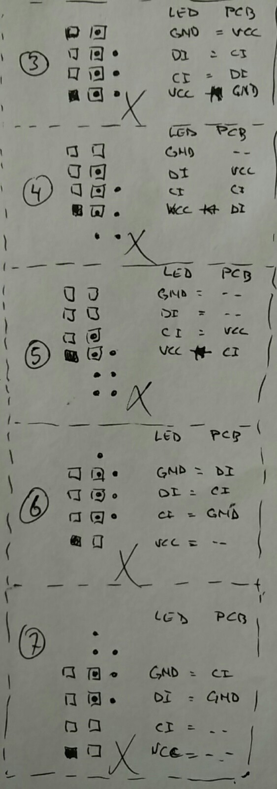
Case 3 - connector rotated 180 degr.:
=> LED’s wire

  • VCC = connected to GND (protected by diode, so safe)
  • Ci = connected to Di
  • Di = connected to Ci
  • GND = connected to VCC

Case 4/5 - connector rotated 180 degr. and shifted ‘up’:
=> LED’s wire

  • VCC = connected to Di (with diode but powered when data is active)
  • Ci = connected to Ci
  • Di = connected to VCC
  • GND = not connected
    .or.
  • VCC = connected to Ci (with diode but powered when data is active)
  • Ci = not connected VCC
  • Di = not connected
  • GND = not connected

Case 6/7 - connector rotated 180 degr. and shifted ‘down’:
=> LED’s wire

  • VCC = not connected
  • Ci = connected to GND
  • Di = connected to Ci
  • GND = connected to Di
    .or.
  • VCC = not connected
  • Ci = not connected
  • Di = connected to GND
  • GND = connected to Ci

Case PCB with opto-coupler:

  • Connection for VCC and GND are checked before data will be started.
  • Of course this so;ution can be made more sophisticated :sunglasses:

with regards,
Willie

and 3 other pictures


We have not tried connecting the pins incorrectly in all of the different variations you mentioned; however, in general, devices can behave unpredictably when connections are crossed. I would not be surprised if plugging them in wrong resulted in damaging the LED segments.

If you need additional protection against making the wrong connections, and cannot find keyed connectors, you could try using something like these polarizing keys to make a connector like you mentioned.

-Brandon

Hi Brandon,
Thanks for your reply.
I first will start to design a failsafe connector-set, before we can get over to order. And of course discuss in our club for permission, because every design will make it more expensive…with approx. 100 buildings
Regards,
Willie