Hi, folks,
I’m working on a mobile (battery dependent) project where the stepper needs to operate intermittently, for long periods of time, under constant load. Basically, the motor turns a couple of degrees, then needs to stay precisely there for some minutes, then turn again very little, then hold that position again for some minutes etc. All those in-between times are basically dead times on which I feel there is much room for energy-efficiency improvement.
-
I need to calculate how many mAH does an X-mAH - spec’ed motor draw in, while maintaining a static torque, when it is under a load that is a given percentage of its holding torque.
-
Is there a way to optimize this “in-between”, static energy drainage? I was thinking about a brake-off (fail-safe) brake of some sorts (a spring-loaded brake that normally is on “brake” mode and which, under current, squeezes the spring and releases the brake). This sort of passive brake would save a lot of energy, I think. Anybody has any experience/ideas with this kind of thing? I did some searches, the prices are absolutely prohibitive for ready-made ones, so I plan on building one myself, and any thoughts/advices are more than welcome!
Thank you,
Eros
Because they rotate slowly compared to a typical brushed DC motor, the current drawn by a stepper motor doesn’t depend very much on the load and under static conditions, not at all. When not rotating, in either case the motor current is the input voltage divided by the coil resistance. If you exceed the manufacturer’s specifications the motor will overheat.
If you want the stepper to hold position when not energized, gearing helps. The best solution is to use a worm gear drive. A properly designed worm gear drive won’t slip even if the motor is not energized.
Hi, Jim, and thank you,
So, from your answer I’m learning that the steppers WILL use 100%, that is the spec’ed Amps, not matter how under-solicited or static it is? In this case, a passive braking system will be all the more necessary.
Currently I’m using a 10:1 speed reduction with a synchronous belt and two pulleys, but that won’t be enough to keep the motor from winding back under a load, if I leave the motor idle.
So my search is on, then, for the simplest to build and cheapest solution for a power-off brake…
Any ideas?
With a good worm gear drive you won’t need a brake. Discarded printers often have them, but also check out the surplus stores for inexpensive options.
For some examples see:
electronicsurplus.com/Item/149893-1.jpg
surpluscenter.com/item.asp?item=13-1478-10-R
Yes, I know about worm gears… and you’re right, they also act as very effective brakes… the problem with those is that they have a backlash that is huge, compared to my needed level of accuracy (I need to turn the motor on the micro-steps level at a time, consistently throughout - it’s for a omni-head time-lapse robot, able to move with precise, extremely small increments at a time)… The minimum amount of backlash can only be achieved with a synchronous belt…
I disagree. In a laboratory setting, for a number of years we used a stepper/worm gear system to orient samples to 0.01 degree precision and much better repeatability, using only a full step motor driver. I have no doubt that if we needed it, we could have achieved 0.002 degree precision and repeatability. The tiny amount of backlash in that system was essentially eliminated by always driving to the final orientation from the same direction.
Hi, Jim,
Well I’ll be using this in the wild, so no controlled laboratory environment 
This is, as I said, for a time-lapse robot.
Let’s assume that I want to shoot a 12 hours time-lapse, one shot every 15 seconds, resulting in 2880 shots.
And let’s assume I want to animate my camera bu rotating it left-to-right encompassing a 30* angle in every direction. This will mean 4 directions (as I have 4 degrees of freedom).
This translates into angular steps of 30/2880=0.0104* - almost spot on what you described.
The problem in my case is that, having a system where I cannot presume to only use a single direction at all times, I need to be very back-lash aware. And, of all the gearing systems, the worm is the most back-lash-prone one.
I found these systems: but they are either impossible to manufacture on a small scale, or prohibitively expensive:
- http://www.antibacklashgear.com/
- http://www.allytech.eu/index_fichiers/Backlashfreewormandwormwheel.htm
- http://urobotics.urology.jhu.edu/projects/BW/
-
http://en.wikipedia.org/wiki/Duplex_worm (which presumes to beat all the above in terms of benefits)
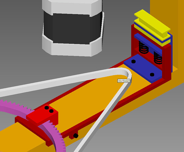
So, if I am to avoid the worm gear idea, my current design - which I hope would take care of the real problem: stopping the motor without backlash - is the one I sketched below, where the yellow piece is a DC electromagnet, the Blue piece is made of magnetically-inert Aluminum and the Red piece is made of steel.
What do you reckon?
Looks like an interesting challenge!
Do you already have a working setup sans brake? If so, does it give the expected resolution and repeatable positioning when fully powered? I’ve heard of difficulties achieving accurate step subdivisions with microstepping controllers.
Hey, Jim,
No, this week we’re starting to purchase/order the parts (RPi, Megatronics, drivers, aluminum profiles, bearings, pulleys and belts, motors).
However we need to decide early on what kind of reduction/transmission we’ll be using, and what kind of brakes, because these choices will determine the choice of motors…
Eros
As a P.S.: I found dedicated stepper motor brakes… but they start at no less than 81-85$ per piece… at 12 pieces, it’s too much.
Also found some fat ass 32 NEMA (a bit too big for my needs) steppers with integrated brakes, at around 97$ per piece after shipping… almost the same deal… too expensive.
http://www.aliexpress.com/item/stepper-motor-with-brake-57BYGH/556948662.html

