I am using the LSM303DLM compass/accel. with a program that cannot utilize the standard I2C library routines.
I have I2C routines that I have written and have used successfully with other I2C devices such as the Parallax compass.
Basically I am utilizing the LSM303DLM example code provided but I am altering the low level routines so they automatically call my routines instead of the provided ones. For example, instead of the provided i2c_stop routine, I want my I2C_Stop routine to be used.
I altered the low level routines using the following #define statements.
I have a reasonable grasp of how the I2C works - when using my routines I use other routines to send a ACK after each read_byte and a NACK after the final read - so it looks like the above substitutions should work since the higher level routines in the example code just use the low level routines to send the proper commands etc to the chip.
I am using the proper pullups, initializing the I/O lines etc… and as I said, they all work fine with the Parallax compass.
All the routines go through their actions and I get back a constant 42 for a heading. I have tried looking at individual vectors for both mag or the acc - all return zero or some constant regardless of the motion or orientation of the chip.
Obviously there is either something I don’t understand about the I2C bus or there is something else I need to do with the LSM303DLM chip. There must be some subtle difference between the library I2C routines and mine… but if mine work with other chips ???
Any ideas or suggestions will be greatly appreciated.
I am sorry to hear you are having trouble getting your LSM303DLM working. Do you have access to an oscilloscope or logic analyzer you could use to see whether the appropriate signals are appearing on the I2C lines? What kind of microcontroller are you using, and how do you have the LSM303DLM connected to it? If you post a picture or diagram of your setup, we can help you check for any visible problems.
Kevin,
Thanks for the help.
The o’scope shows noise-free pulses going from 0 to 4.8 volts or so. When I interrogate the compass in a loop I see constant activity on both the clock and data. As I said the same I2C routines work with the Parallax compass so I am assuming my problem is with some subtle differences between the I2C needs???
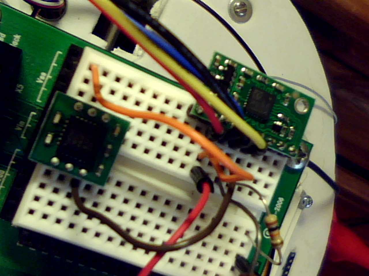
The photo shows both compasses side by side - both powered by the same supply. I just move the clock and data lines from one compass to the other to test each. I have 10K pull-up on the bus, but get the same results with the internal pull-ups -besides the scope shows perfect pulses.
I am driving the compasses with a Baby O, but for other reasons I must use my own I2C routines.
There does not appear to be any special timing or delays needed for the LSM303 compass - but I am using Pololu’s higher-level routines so one would think all would be there. The ONLY thing I am changing is the low-level routines(start, stop, read a byte, etc) and all these routines work with other devices.
I suspect it is something simple, but I just can’t see it…
Are you able to communicate with the LSM303 using our unmodified low-level code? It would be good to try this, even temporarily, to see whether the problem lies with the hardware or your code.
Kevin,
Yes, the orginal low level routines do work fine.
When testing them I used all my code for commication with the PC etc… I just comment out my #define statements so your original low level routines will be used… everything works fine.
My low level routines work with other I2C devices and I have gone through the spec sheet as well as all the Pololu example code and the functionality of everything seems identical. Obviously not though.
Since I am using the same upper level routines in both cases I know all the addresses and codes are correct.
The hardware is fine - I just move the clock and data wires to new pins - no other differences.
It would seem that my #define statements are not mapping the my routines properly.
START and STOP should be the same… as with READ and WRITE… I added ACK and NACK as shown in the code (as per the bus standard and the compass spec sheet - I assume they are done inside your low level routines.
I have tried removing them… nothing I do seems to have any effect.
Ideas???
I suspect that your code is just doing something differently enough with regards to timing or speed that the LSM303 no longer recognizes it as acceptable I2C communication. (What I2C frequency are you using?) The procedure for debugging this should be straightforward; just make one small change at a time to gradually replace our code with yours and see when it stops working. You will probably find it useful to capture the I2C signals with your oscilloscope the whole time you are doing this so you can see exactly what is changing.
Great idea.
I will start by changing only part of my substututions… for example, use my START and STOP but your READ and WRITE etc.
I will let you know what I find out.
It is currious as my routines work with other I2C devices - just not yours.
As for frequencies, everything in mine is bit-banged. No timers or interrups either. So I can add delays to slow the or speed the transfers. Here are my routines just for your information
One big advantage they have is that I can use ANY pins for the clock and data and I never have any timer conflicts.
void I2C_Start(void)
{
  //I2C start condition.  SDA transitions from high to low while the clock is high.
  //Assumes SDA and SCL are both floating high
  SetSDA_Output();  //Pull SDA low
  SetSCL_Output();  //Pull SCL low
}
//=================================================================================
void I2C_Stop(void)
{
  // I2C stop condition.  SDA transitions from low to high while the clock is high.
  // Assumes SCL is held low
  SetSDA_Output();     //Pull SDA low
  SetSCL_Input();      //Let SCL float high
  SetSDA_Input();      //Let SDA float high
}
//=================================================================================
void I2C_ACK(void)
{
  //Acknowledge for read; use between reading successive bytes
  SetSDA_Output();     //Pull SDA low
  SetSCL_Input();      //Clock out an acknowledge bit
  SetSCL_Output();     //
  SetSDA_Input();      //Let SDA float high
}
//=================================================================================
void I2C_NACK(void)
{
  // Non-acknowledge for read; use after reading last byte
  SetSDA_Input();      //let SDA float high
  SetSCL_Input();      //Clock out an acknowledge bit
  SetSCL_Output();     //
}
//=================================================================================
int I2C_Read(void)
{
  //Read a byte from the I2C device I2C_ReadByte will hold the read byte
  int I2C_ReadByte = 0;
  int i;
  SetSDA_Input();                         //Let SDA float
  for( i=0; i<8;i++)
  {                                       //for 8 bits starting with the MSBit
     I2C_ReadByte = I2C_ReadByte << 1;    //shift last read bit to left
     SetSCL_Input();                      //let SCL float
     if(PINB &(1<<SDA_PIN))               //read port and mask for SDA pin
       I2C_ReadByte++;                    //if high then increment to set bit
     SetSCL_Output();                     //Pull SCL low
  }
  return I2C_ReadByte;
}
//=================================================================================
int I2C_Write(int I2C_WriteByte)
{
  //Write a byte to the I2C device I2C_WriteByte is the byte
  //to write and I2C_AckBit will hold the Ack from slave
  int i;
  for( i=7;i>=0;i--)
  {                                //for 8 bits starting at the MSB
    if (I2C_WriteByte&(1<<i))                //examine bit in the Data byte
      SetSDA_Input();                 //if high then set SDA to input ie floating => high
    else
      SetSDA_Output();                //if low then make SDA output and thus low
    SetSCL_Input();                   //Pulse SCL high then low
    SetSCL_Output();
  }
  SetSDA_Input();                     //Let SDA float
  SetSCL_Input();                     //Start a pulse on SCL
  i = 0;
  if(PINB & (1<< SDA_PIN))            // read the SDL pin for the ack status
    i = 1;                            //set i to 1 if SDL is high
  else
    i = 0;
  SetSCL_Output();                    //Finish a pulse on SCL
  return i;
}
Kevin,
I’ve watched all the data on a scope… it seems that no matter what I do with my bit-banging routines the compass does not want to respond even though other I2C devices respond fine.
I am ready to look at alternate solutions.
The reason I could not use your routines is that I need all 8 analog pins for other uses.
Is there an easy way to modify your routines to use other pins on another port?
ALSO, when I run the routines with your code, they do work, but the readings generally vary by 5 or 6 (sometimes even 10 or more) degrees even when the device is stationary. Is this normal? I realize that calibration will improve the accuracy, but if the compass is at rest shouldn’t the reading be constant or at most one degree off of the previous reading.
Thanks
As you mentioned, and as your code shows, you are doing your I2C bit-banging essentially as fast as your microcontroller allows, so I would not be surprised if it is going faster than the LSM303 can handle. Have you observed the differences in speed between your routines and ours with your scope? If your routines are going a lot faster, could you try adding delays to slow them down to match ours?
Our routines use the hardware I2C (TWI) on the ATmega328, which is tied to pins PC4 and PC5, so they cannot be remapped to different pins.
It is hard to say whether the performance you are seeing from the LSM303DLM is normal, but I expect that calibrating (using the right offset constants for the magnetometer readings) will improve the accuracy somewhat. Also, our Orangutan example code for the LSM303 chips is actually for the older LSM303DLH, which has some slightly different register addresses (I believe the magnetometer Y and Z addresses were swapped). Did you fix this in your code to use it with the LSM303DLM? If not, that might account for some strange readings reported by the program.
I will try to get a modified version of the program that will work with the LSM303DLM up on our site shortly.