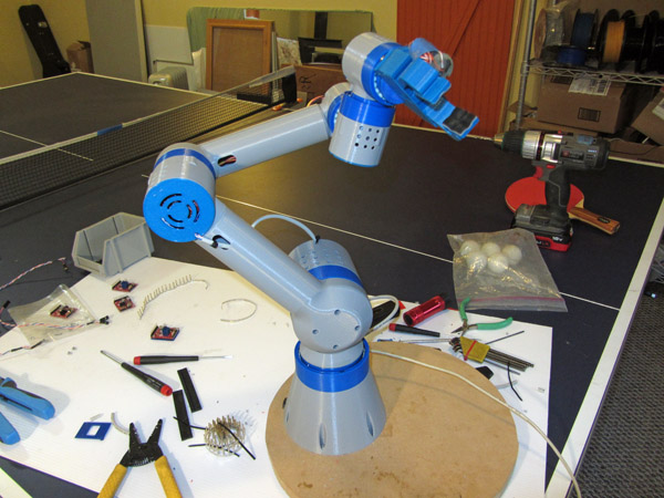
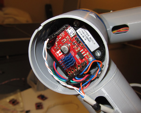
I started working on the 3D printed 6-axis robot arm shown below, but I needed a stepper controller that would: 1) support coordinated motion of at least 6 axes, and 2) be small enough to distribute inside the arm structure to minimize the wiring headaches. The Tic T500 is an ideal size, but it doesn’t support coordinated motion. So wrote my own alternate firmware for the on-board PIC18F25K50 processor. It uses a path point buffer that allows the host (in my case, a PC) to load multiple controllers with path data and then simultaneously start the motion of all motors. Here’s a link to a folder containing the firmware source code and HEX file, source code and executable for a Windows test utility program, and a PDF document describing how the firmware works: TicStep Files
Note that this involves programming the PIC18F processor directly, overwriting the standard Tic firmware (including the bootloader) – there is no turning back! You’ll need a PIC in-circuit programmer (like the PicKit 4) to program this new firmware. Please note also that Pololu does not support this firmware (although I’m happy to answer questions), and using it will undoubtedly void any warranty. As for my part, I offer no warranties either - use at your own risk. Please let me know what you think!
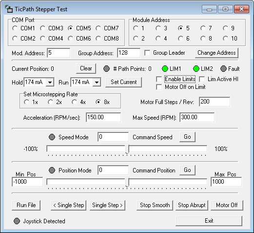
And here is a screen shot of the Windows test utility for testing the firmware on multiple controllers:
Wow, that’s an amazing robot arm you’ve created!! Congrats!! I’m using the Tic-500 to control a macro photographic setup for imaging small subjects (chips for example). I understand what the multi-axis coordination requires, and ended up doing such in Python running on a Raspberry Pi. Your solution is much better, but if you follow the threads below I’m not a software or computer person, and EE (design chips)… so reprogramming the Tic not going to happen for me! I even asked Pololu about putting 3 Tic-500 equivalents on a single PCB and having 3 USB connectors, but that wasn’t a great idea unless they used a single USB which meant they had to create the new code like you’ve done. You might want to ask Ben about this, maybe they could use your code?
I had thought of using an Arduino, but decided on the Raspberry Pi since it seemed easier to work with to develop the code, and my total lack of software & computer skills.
Anyway, what you’ve created is very impressive, so hats off
BTW really nice GUI, that’s something I’d thought about but have no idea where to start. I’m just running from a Python shell, which works OK but nowhere as elegant as your GUI…so another hats off
Thanks, Mike! Yes, it would be really nice if Pololu either integrated this feature into their standard firmware, or else offered it as an alternative that could be loaded using their bootloader. Not many people are willing or able to completely re-flash their Tic firmware. I’ve talked to them about this option, but it might take a few customers like yourself expressing interest for them to offer it.
That looks like a really nicely done project and we’ll be looking into it more carefully soon. It looks like you put a lot of effort into making the Tic work and documenting everything. Thanks for sharing it.
I’ve sent a note coping these comments off to Ben at Pololu, so we’ll see where this goes. What did you use to create the GUI, is this difficult for a no computer/software skills noob like me?
Mike,
For the test program GUI, I used C++ Builder. There is a community edition you can download for free. I’m not much of a programmer myself, but I’ve used C++ Builder for years (decades, actually) and find it’s pretty easy to quickly put together little programs like this for my own use. And thanks for putting in a mention to Ben@Pololu about this.
-Jeff
Here is a video of the robot arm shown above that uses seven of the Tic T500 stepper drivers with my custom firmware that supports coordinated motion. The arm is almost entirely 3D printed, including the compound planetary gearheads at each joint. I’ll be posting the design on Thingiverse once I get all of the documentation together. In the mean time, I’m happy to answer any questions.
Hi Pololu Members, Can you please opensource PIC18F25K50 firmware for tic drivers? Or send me on my email “Yasirshahzad918@gmail.com” As I wanna to customize it according to my needs, thanks
Hi @BrandonM@nathanb Can you Please tell me how do you people set the current limiting Ref voltages from PIC18F25K50 on RA2 gpio? I’m totally amazed that gpio can set some Ref voltages. May be you’re using DAC for this purpose. am i right?