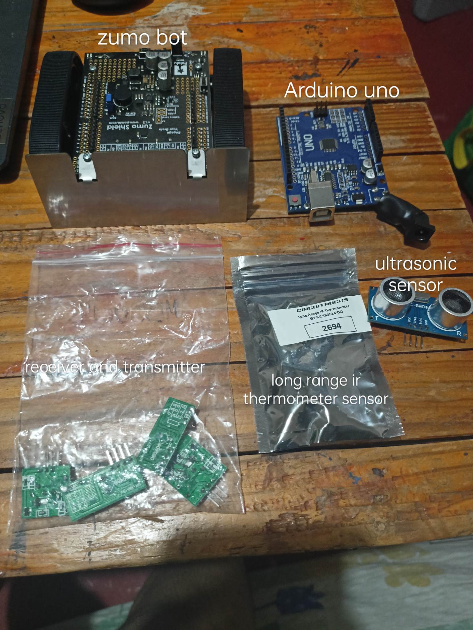
Hello, Good day everyone. I want to know whether it is possible to add ultrasonic sensor (hc-sr04), a long range ir-thermometer sensor (mlx90614-dci), and camera module for Arduino (OV-7670) on the zumo robot.
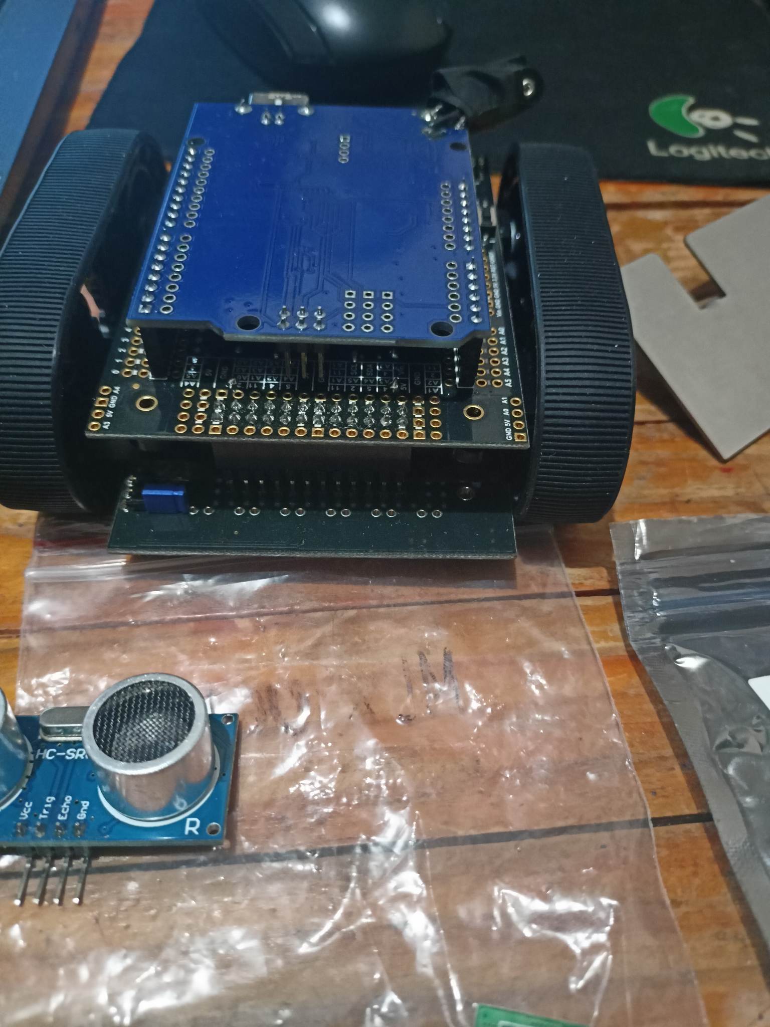
(If you are wondering why the Arduino uno have the port soldered like that, the reason is because the 9v port is hitting the zumo robot, which is why I need to solder it like that so that I can mount the uno to the zumo bot v1.2)
Anyways, when I mount the uno to the zumo bot, I don’t know where to put the sensors anymore?
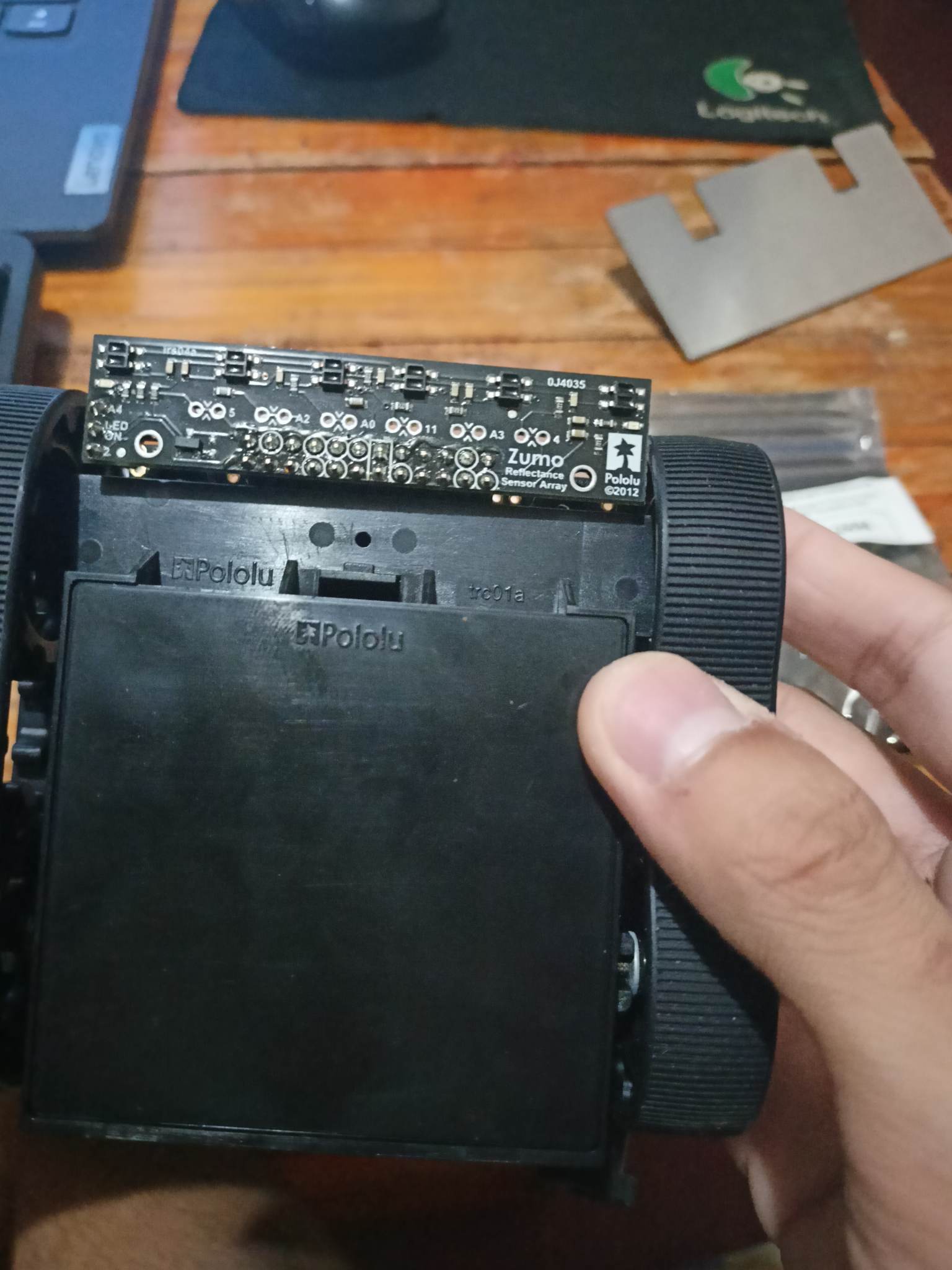
Do I need to remove this whole reflective sensor array and solder the wires there? I don’t know what to do. Answering my questions would be very much appreciated.
it is possible to add additional sensors to the Zumo Robot for Arduino, but you may need to consider how to physically mount the sensors and connect them to the Arduino board. Using a breadboard or custom PCB can provide a flexible solution for connecting multiple sensors, while allowing you to keep the reflective sensor array intact.
I think making your own chassis using the pololu motors and wheels like this, will be easier:
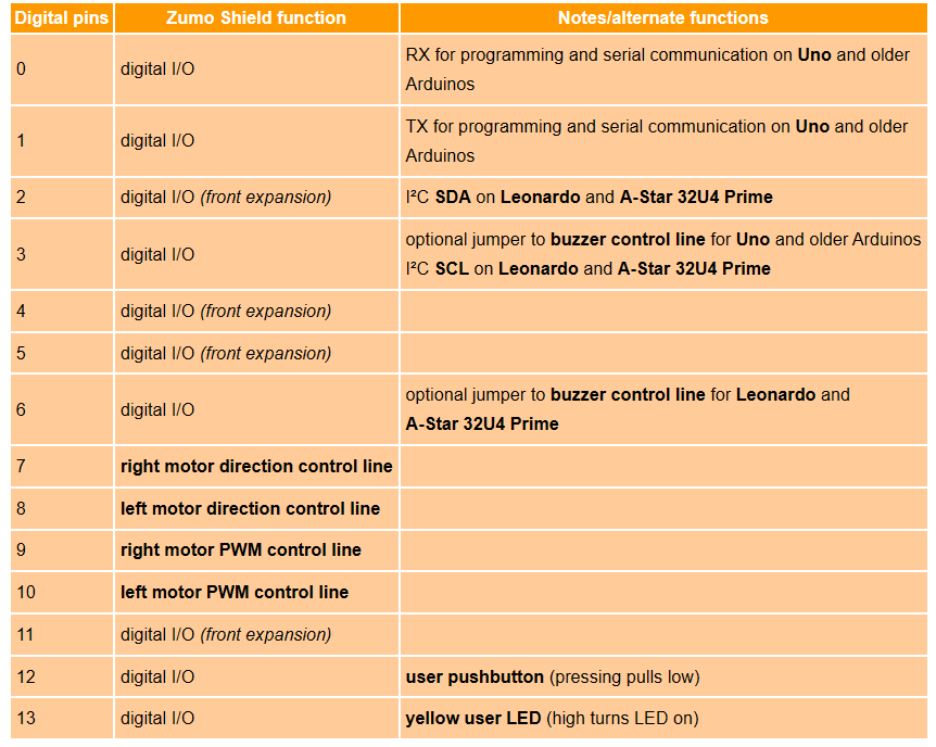
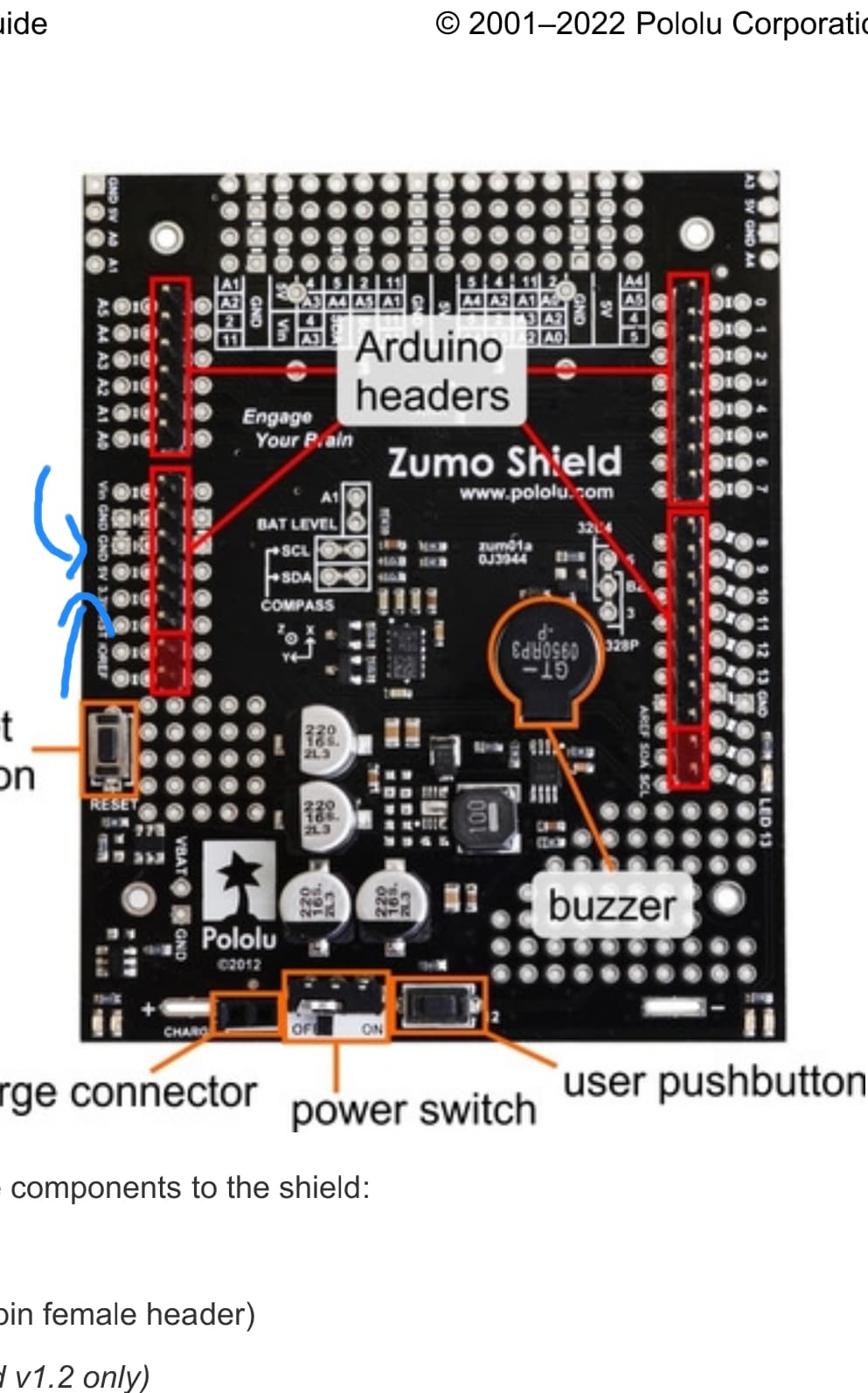
To add additional electronics to the Zumo, you will first need to make sure there are available pins that are capable of reading the appropriate signals and determine which of those pins you want to use for each device. You can reference the “Arduino pin assignment table” section of the Zumo Shield for Arduino user’s guide to see what each pin is used for. Please note that some pins have optional functions specific to different Arduino boards; for example, pin 3 is used by the Arduino Uno to control the buzzer, but you can remove a shorting block jumper on the board to disable the buzzer and free that pin up for other uses. Additionally, if you are using the line sensor board, that uses pins 5, A2, A0, 11, A3, and 4, but you can find information about disabling or remapping these in the Adding a Zumo reflectance sensor array (optional) section of the guide.
Once you figure out which pins you want to use, you will need to locate them on the board. The pins are labeled on the silkscreen and most of them are available in at least 2 locations: the front expansion area and the pins along the sides of the shield (near the Arduino headers). You can find more information in the “Front expansion” section of the guide.
Depending on where you want to solder wires, you will likely need to partially disassemble the robot or remove the PCB from the chassis.
Thanks. Just a follow up question. Is it possible to make the robot move if I didn’t exactly mount the Arduino uno. I mean, if I just connected the motors of the zumo bot to the Arduino, and the arduino have the program:
void setup() {
// set pins 9 and 10 as output
pinMode(9, OUTPUT);
pinMode(10, OUTPUT);
}
// make the motor move forward
void loop() {
digitalWrite(9, LOW);
digitalWrite(10, LOW);
}
In the arduino pin assignment table, is it possible to use digital pins 0-3, 6, 12, and 13 to add other electrical components like sensors? What is the use of these digital pins?
If you want to control the motors through the Zumo shield, you will still need to provide the following connections:
M1DIR (pin 10 on the shield)
M1PWM (pin 9 on the shield)
M2DIR (pin 8 on the shield)
M2PWM (pin 7 on the shield)
GND
5V
The code you provided would not be enough to make the motors move. You would need to drive the M#DIR pins high or low to specify the direction and send a PWM signal to the M#PWM pins (the duty cycle will determine the speed so a digital high signal would be the same as a 100% duty cycle). However, please note that if you make the same connections that the shield would have if it were mounted, you could still use the ZumoMotors functions from our Zumo Shield Arduino library.
Pins 0 and 1 are the hardware serial pins on the Arduino Uno (RX and TX), and are used for programming, so if you try to use them, you might need to disconnect them while programming so it doesn’t interfere.
If you are using the reflectance sensor, there is an optional jumper on it which uses pin 2 by default to control the emitter for the line sensors. You can free this pin up by removing the jumper and calling using the QTR_NO_EMITTER_PIN initialization parameter: reflectanceSensors.init(QTR_NO_EMITTER_PIN). You can find more information in the Adding a Zumo reflectance sensor array (optional) section of the Zumo user’s guide.
On the Uno, pin 3 is used to control the buzzer; as I mentioned in my previous post, you can remove the jumper on the board to disable the buzzer and free up this pin. You can find more information about the buzzer control jumper in the Jumper settings section of the guide.
The Zumo shield does not use pin 6 when used with the Uno.
Pins 12 and 13 are used for the user pushbutton and onboard LED, respectively. So you can generally use them for other things, but be mindful that you should probably not push the button (which shorts pin 12 to ground) or try to control the LED while doing so.
So does this mean that pins 0 and 1 are really necessary and indespensable? Also. Which pins are the 5V and GND pins present in the zumo bot to make the motors. Are we supposed to connect a wire from the 5V GND hole in the zumo bot to the Arduino just to make it move?
Pins 0 and 1 on the Arduino Uno are the hardware serial pins. Hardware serial is used for programing the board, so if you have anything connected to them while the trying to program, it could interfere and cause problems.
When used as intended (with the Arduino mounted on the Zumo shield), the Zumo’s motor driver gets its logic power supplied from the 5V pin on the Arduino. So, if you are making the connections separately, you will need to supply a connection from the Arduino’s 5V pin to the Zumo shield’s 5V pin, and from one of the ground pins on the Arduino to one of the GND pins on the Zumo shield. All of the pins labeled “5V” on the shield are connected internally on the board, and all of the pins labeled “GND” are connected internally, so it does not matter which ones you use to make those connections.