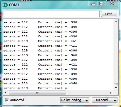
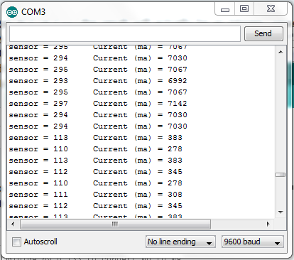
I’ve written a simple sketch to retrieve the amount of current flowing through the ACS715. Difficulties are the apparent negative readings for milliamps when low current is flowing, and non zero output when no current is flowing. Serial monitor capture is attached.
/* This sketch describes how to connect a ACS715 Current Sense Carrier
(https://www.pololu.com/catalog/product/1186) to the Arduino,
and read current flowing through the sensor.


Vcc on carrier board to Arduino +5v
GND on carrier board to Arduino GND
OUT on carrier board to Arduino A0

Insert the power lugs into the loads positive lead circuit,
arrow on carrier board points to load, other lug connects to
power supply positive

*/

int analogInPin = A0;  // Analog input pin that the carrier board OUT is connected to
int sensorValue = 0;        // value read from the carrier board
int outputValue = 0;        // output in milliamps

void setup() {
  // initialize serial communications at 9600 bps:
  Serial.begin(9600);
}

void loop() {
  // read the analog in value:
  sensorValue = analogRead(analogInPin);
  // convert to milli amps
  outputValue = ((sensorValue * (5000/1024)) - 500)/0.133;
/* sensor outputs about 100 at rest.
Analog read produces a value of 0-1023, equating to 0v to 5v.
There's a 500mv offset to subtract.
The unit produces 133mv per amp of current, so
divide by 0.133 to convert mv to ma

*/
  // print the results to the serial monitor:
  Serial.print("sensor = " );
  Serial.print(sensorValue);
  Serial.print("\t Current (ma) = ");
  Serial.println(outputValue);

  // wait 10 milliseconds before the next loop
  // for the analog-to-digital converter to settle
  // after the last reading:
  delay(10);
}
However, there are many quirks about arithmetic in C/C++ that will cause you problems.
When you divide an integer by an integer in C or C++, the result will actually be an integer, rounded down. So “(5000/1024)” is actually 4, which is way off from the value of 4.8828125 that you wanted. Some people resort to floating point arithmetic to fix this, but floating point arithmetic is very expensive on an AVR. A simpler solution is to multiply sensorValue by 5000 and then divide the product by 1024. I think you should cast to “long” (32-bit int) to make sure no overflows happen in the multiplication. So now we have:
That code should work for you, but because you wrote a floating point literal “0.133”, your program will still be doing floating point arithmetic. An easy way to fix this is to change “/0.133” to " * 1000 / 133 ":
You can point out to your readers that “((long)sensorValue * 5000 / 1024)” has a physical meaning on its own; it’s the voltage on the sensor’s output in millivolts.
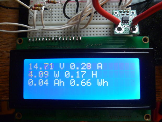
I’m adding volts, watts, amp hours and watt hours next. See http://arduinotronics.blogspot.com/2012/04/monitoring-power-consumption-with.html as the project progresses. I’m a ham radio operator in EmComms (Emergency Communications), and this battery capacity meter will allow us to keep tabs on power consumption and battery capacity in a grid down scenario.
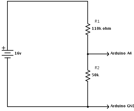
The one thing that concerns me is the accuracy of the voltage divider, and it’s constant “wandering”. It’s reading low, and wanders around constantly by a half a volt or so, like there’s noise on the line. Any ideas?
  batVal = analogRead(batMonPin);    // read the voltage on the divider
  pinVoltage = batVal * 0.00488;       //  Calculate the voltage on the A/D pin
                                    //  A reading of 1 for the A/D = 0.0048mV
                                    //  if we multiply the A/D reading by 0.00488 then
                                    //  we get the voltage on the pin.

  batteryVoltage = pinVoltage * ratio;    //  Use the ratio calculated for the voltage divider
                                          //  to calculate the battery voltage
The ADC on an AVR can’t very accurately measure signals with a high output impedance, and your voltage divider definitely counts as high-impedance. From the ATmega328P datasheet:
I think you’ll have better results if you make your voltage divider resistors smaller, such as 10k and 5k, though this would waste 10 times more power (maybe 1.6 mW for your current configuration vs 17 mW for the new one).
I have 4 possible nominal battery bank voltages. Each battery bank has a higher possible charge voltage during certain charge cycles. I’ve called this max, and will prevent a voltage of over 5v being presented to the Arduino pin during all charge cycles including equalize.
Solving for R1
R1 = ((R2*Vin)/Vout)-R2
with a R2 of 5k ohms, I get the following values of R1 for 4 battery voltages:
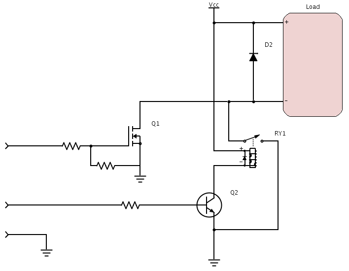
I’m adding a low voltage disconnect circuit with a hybrid relay (eliminates MOSFET heating and relay arcing) to protect the battery from excessive discharge. When sketch starts, the MOSFET is enabled, then the relay. Upon voltage drop below predermined value, the relay drops, then the MOSFET. Use a SSR for an AC Load. Full instructable at http://www.instructables.com/id/DIY-Amp-Hour-Meter-Arduino/.
If you have an input impedance problem, you can buffer the input signal with a single-ended opamp, such as an MCP601 or similar. Tie the output directly to the - terminal as well as the Arduino input pin, and the input to the + terminal.