Hello …I have an EleksmakerPro A3 2,5 watt Laser cnc machine…Using GRBL 1.1e …ManaSEver3.2 controller
A4988 stepper drivers @ 1/16 step…VREF 0.5 volts
1.2 amp stepper motor @ 2.4 ohms
After I fine focus my beam the dot size is 9 distinct lines in 1mm (0.11 mm)
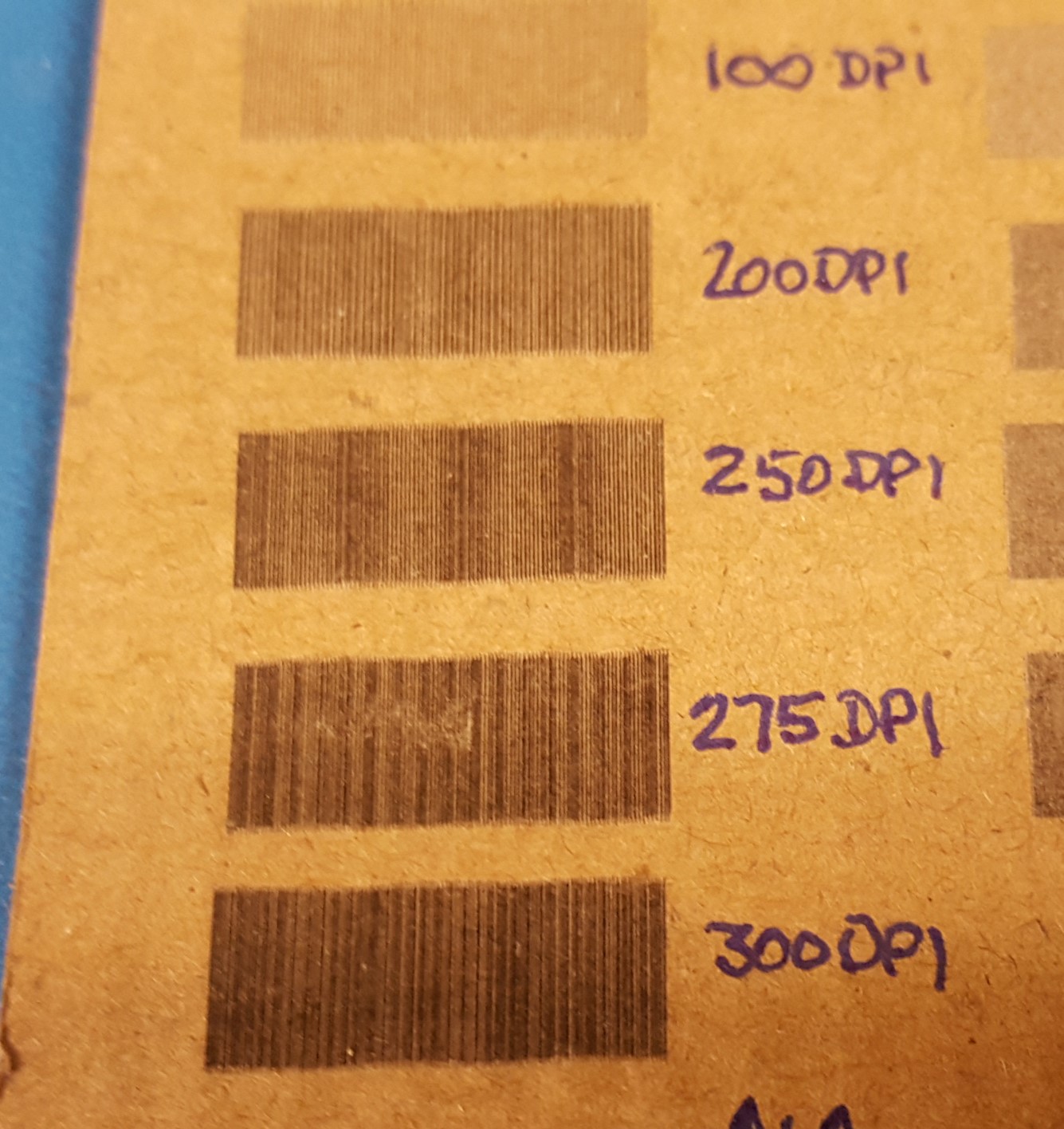
I then scan a 5mmx 10 mm rectangle at 1500 mm/min @ 250 dpi (0.1 mm)…
The resultant image has "banding " distinct dark and light horizontal bars
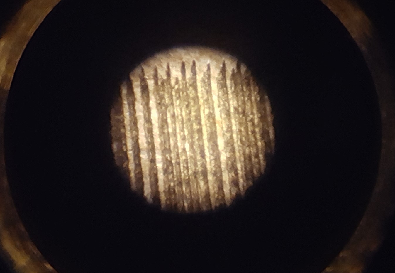
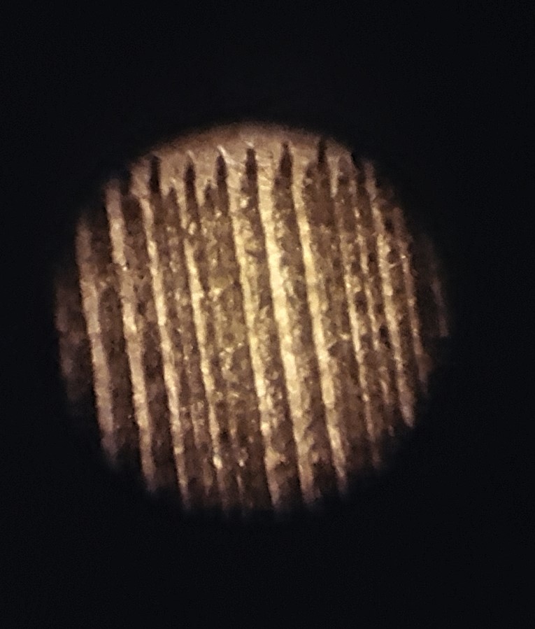
Looking at them under a x30 lens you can clearly see the lines slowly getting close, overlapping the spreading apart
At first I thought a hardware issue,but not so…
I then took the Y steppers off and made “clocks” with them using a thin piece of doweling for hands and a polar graph for the face…I then video’d the movement through one revolution
Went into a video editor and moved one frame at a time …marked down the number “ticks” the dowel moved
the ticks were not regular moving from 0.5 to 1.5 …but this “uneven movement”
was cyclic
I have replaced stepper drivers…Nano…control board…Power supply
Still the problem exists…for now to “get” by I de-focus the beam
Any suggestions greatly appreciated
Thanks
Hello.
Which of our A4988 carrier boards do you have? What current sensing resistors are on them? Can you post pictures of them so we can identify them? How far off from the expected position is the actual position? Is it a few microsteps or several full steps?
-Nathan
Hi Nathanb
I have 4,boards, 2 new spares and two original,have tried all 4 with same results
Also have tried brand new Mana SE control board
looking with x30 lens I can count 10 lines in a 1mm width…so beam is approx 0.1mm
the above photos of scans (5 mm x 20 mm) with x 30 lens you can overlaps and spaces that vary in a cyclic fashion dark areas where they overlap and lighter areas where there are spaces between scans
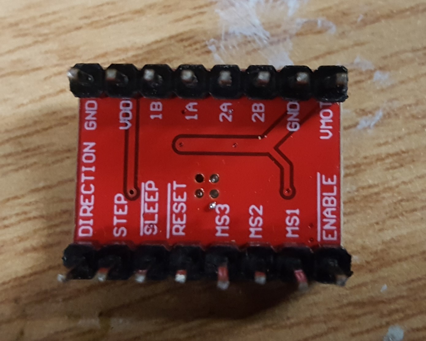
please find attached photos of stepper modules
thanks
signal going to one coil of stepper…duty cycle seems to be changing
Thank you for posting additional photos. Those are knockoffs of our A4988 carrier boards. For information about setting the current limits, you should contact the manufacturer of your system.
In general, when microstepping, the current through the coils of the motor should form a sine wave, but the driver connects and disconnects the coils to the power supply to maintain that current, so looking at the voltage at the coil output terminals probably will not be that helpful.
-Nathan
Thats it,The x is set at 0.6 the y at 0.5…you.ve never seen this before…no suggestions no path forward???
Nathan helpfully suggested that you contact the manufacturer of your A4988 knockoffs, to determine how to set the current limit properly. It is absolutely essential to do so, if microstepping is to work at all.
Looks like the knockoff uses 100 milliOhm current sense resistors.
1 Like