I was working on a project and needed a board to make the task of calibrating the stepper motor drivers a quicker and easier process. It uses an ATX power supply, an Arduino, and a computer with a usb port.
When I was designing the board I thought it would be beneficial to expose all of the stepper driver pins to the Arduino (except the reset and sleep). After building the board and playing with it, I thought of all the people on the forums who needed a bit of a scaffolding to get up and running with the stepper. (I was one of those people not too long ago.) So I threw together a little Arduino program that lets you quickly test out all the features of the stepper driver using the dev board. After that I decided to offer the board for others to purchase.
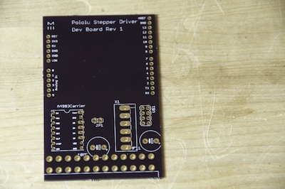
Here is the board itself:
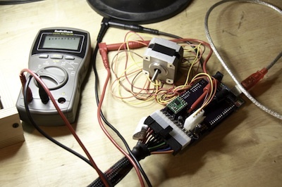
Here is me using it with my DMM to tune the current on the board:
With that purchase I will email you a BOM (Bill Of Materials) showing where you can get all the components from a single supplier.
If you are more interested in a kit or fully assembled board, just email me for a quote.
This board is for the A4988 stepper driver only.
I have attached the Arduino sketches to the page for everyone to use.
I would strongly suggest this board to people who are interested in prototyping what they want to do with the stepper driver. It is the fastest way to let you connect it to a motor to find out if what you need to do can be done with the driver. You will quickly be able to see what stepping mode you want to use. You can even use the board after you are done prototyping, since you can use it to quickly tune the current for your subsequent drivers.
I have also attached my Arduino sketch: StepperDriverDevBoardShell.zip (1.78 KB)
which allows you to interact with the arduino as a shell.
Turn on the Newline on your Serial Monitor.
Then use one of these commands:
ChangeDirection
EnableStepper
DisableStepper
SteppingOn
SteppingOff
FullStep
HalfStep
QuarterStep
EighthStep
SixteenthStep
It is pretty fun to be able to interact with the driver in real time.
I posted a video of what the experience is like using the stepper driver board in general and more specifically what it is like with the dev board and the Arduino sketch I provided.
In honor of thanksgiving ( and black friday ) I have decided to upload all the files related to this board.
All files are covered by the :
Creative Commons Attribution-ShareAlike 3.0 Unported License.
I am uploading a new Arduino sketch which allows you to also control the stepping speed of the motor through the terminal for quick turnaround.
Now you can do:
SteppingOff
EighthStep
StepsInHz=1500
SteppingOn
And quickly see what your motor can handle.
void setup() {
}
// We set the enable pin to be an output pinMode(enablePin, OUTPUT);
// then we set it HIGH so that the board is disabled until we // get into a known state. digitalWrite(enablePin, HIGH);
Serial.begin(9600);
Serial.println(“Starting stepper exerciser.”);
pinMode(stepPin, OUTPUT);
pinMode(dirPin, OUTPUT);
void loop()
{
int j;
// set the enablePin low so that we can now use our stepper driver.
digitalWrite(enablePin, LOW);
// wait a few microseconds for the enable to take effect
// (That isn’t in the spec sheet I just added it for sanity.)
delayMicroseconds(2); // we set the direction pin in an arbitrary direction.
digitalWrite(dirPin, HIGH);
It is immediately obvious that the code you posted won’t compile, so I’m pretty sure that is not the program you are running. Can you post your actual code, and please be sure to the [ code ][ /code ] tags (without spaces) to format your post so it is easier to read.
What kind of battery are you using (e.g. are you using two [url=http://en.wikipedia.org/wiki/Nine-volt_battery]9V batteries in parallel)? How did you set the current limit? Can you describe all your connections?
So this is a 400 step motor. This code turns 180 degrees clockwise then 180 degrees counter.
How do I control the speed?
DelayMicrosends(1000) makes the motor spaz in one place using any other setting besides 1000… why?
I am hooking up a 18v cordless drill battery straight to the board. You mentioned how am I controlling current… doesn’t the driver board do this? is what I am doing bad?
Setting enable pin High/Low (I am not using) sleeps the motor Low? should I do this to save battery life when I do not want the motor to move (but not stand firm at one position)?
Must I always delaymicroseconds(2) between steps?
Ben, I have read many responses to your posts and I must say you are a very patient man. I thank you in advance for your patience with me and any guidance.
While playing around with this more, I discovered the code mentioned in my last post does not create a steady back and forth motion. For example it may rotate forward and backward a few intervals then go forward 2 intervals then maybe 100 steps backwards.
I suspect maybe it is a power issue? I’ve played with every delaymicroseconds() instance with all sorts of numbers and nothing makes it consistent.
So I need to add I’m new at this.
Based on the motor schematic I posted in the first post it shows a voltage at 3.06 and a current at 1.7 amps.
If I have an 18 volt cordless drill battery, how do I rig this?
Also, I bought 2 of these motors and 2 A4988 boards. The other board won’t even power either motor to even spin. Solder joints are solid. I’m very confused. So confused I bought 2 spark fun boards to try them. I would rather use these based on the amp range so please help.
I realize it’s holiday time but I’m getting desperate.
Thank you.
Why doesn’t someone just do a tutorial with a specific Fritzing arduino pinout and a common battery/ common motor with simple code instructions for the not so knowledgable people? By trade I’m a C# coder for the past 10 years. You can find anything on the web for .Net code.
What a great service you’ve performed posting both this and your pdf “getting started guide”.
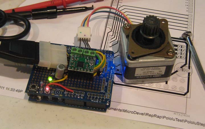
While my wife, daughter, and grandkids were watching Christmas movies yesterday, I soldered your circuit on a Sparkfun prototype board, with only the most minor of changes. I added LEDs to monitor 5V and 12V and used a PC Peripheral power connector instead of a motherboard connector. I even used the same Arduino pins as you did and your code worked right away.
My stepper started to pause then restart then pause, and I knew to turn down the current. Once I could find something that fit that little pot, that problem was fixed. I put my meter in series with one of the coils, sent SteppingOff, read the amps, and turned it down more. Easy! Fun! Wow!!
All the commands work great (although they are a bit verbose and mixed case - YOU must touch-type).
Thanks again and Merry Christmas to you, too! (notice your .brd underneath)
Bendage,
Now that mine works, I feel more qualified to speak to your problem. My GUESS is that your A4988 is overheating and stopping until it cools, then restarting. This would cause it to drop out sometimes and not other times. That pattern overlays on your forward and backward motion to act in the way that you see.
Another indication is your 1.7A - without a heatsink the A4988 can’t continue to do that much current. The validity of your measurement depends upon your method of measuring, so I suspect 1.7A is LOW. The fix: turn the pot counterclockwise until the motor doesn’t turn at all, then back just until it turns smoothly again.
Please give feedback on the results.
BTW: .net and C# are evil - they tie you to one software platform and make you relearn that platform with their continuing changes. Just say “NO” or perhaps “H*LL NO”! If you dig ditches instead, at least you can pick your own shovel and can dig ditches for different vendors and purposes. (IM!HO where ! is used as a logical negation operator, but you knew that.)
I am very new to stepper motors and will trying using one to drive a peristaltic pump with my arduino and pololu A4988. This thread has been very helpful, but how do I know the ideal amperage to run my motor at?
The answer to your question depends on your stepper motor. You do not want to go above the rated current for your motor. Also, you cannot exceed about 1A per coil with the A4988 unless you cool it. If power is not a concern, you probably want to maximize your current given these two constraints. Otherwise, you will have to experiment to find the ideal current for your application.
The ideal current is the least that gets the job done, up to the maximum that your motor can take OR the maximum heat you can tolerate being generated. It depends upon your stepper, your power supply, the speed of your steps, and the torque your pump needs. Torque goes down as the current goes down, or as the number of steps/second go up.
For example, from looking at the spec sheet for your motor you see it is rated for a 1A current. That is a maximum and the motor will get quite hot if you go there. That is also near the limit of the A4988, depending upon cooling. There will probably be a chart that shows torque vs speed with different lines for different currents. This will give you a feel for the relationships for your stepper.
Test it and see if 1/2A is enough to turn your pump. Turn down the current more until you find it doesn’t move your pump. You won’t hurt the motor by “stalling” it this way. Now turn up the current until the motor runs smoothly and quietly. Remember, you can only read the current with a meter when it isn’t stepping. If you need the full 1A continuously, you probably will have a heat problem.
Don’t forget to disable the stepper when you don’t need to move it (unless you need holding torque). This will limit the power used and heat generated. A stepper will consume all the power you give it just to hold itself in place, if you let it or if you want it to hold.