Unfortunately, selecting the capacitor that is right for your application is beyond the scope of help I can provide. We have an article on the related topic of LC spikes, which you might find interesting. Generally, the values you have been talking about sound reasonable to me.
OK so this may be a dumb question. I need to run my servos at 1.5A using an A4988, so I need measure at the measure point for .6V. I can’t get the potentiometer to make any change in my reading, it simply hovers at .02V nomatter where I put it or what direction I spin the POT. Where does the other end of the DMM connect to when reading? What could I be doing wrong?
In response to b.allen, and leading to a parallel question, I connected 5V (and Gnd, 0V, of course) and measured the voltage at the test-point mentioned on the Pololu A4988 main page.
It measured something like 0.75V - give or take a foot. Now the current sense resistors are 0.05Ω so that sets the nominal current at I= V/R = .75/.05 = 15 Amps, just slightly excessive.
For b.allen’s application, he will need one tenth of that (1.5A against 15A) so will need only 0.075 (75mV) at the test point.
I’m aiming for a half-Amp so need only 25mV, and the potentiometer is nearly off the bottom of its range. In fact it jumps from 10mV to 40mV at the merest hint of movement.
Since the maximum current is 2A, and this forum talks a lot about that, might I suggest the potentiometer should be replaced (by Pololu, at manufacture) with one that ranges from 10 or so, to only (2A x .05 Ohm ) 100mV max?
At the same time (Mk XIV) bring the test-point out to the board-edge or a large-enough via/peg that we could connect a croc-clip to it.
Thank you for your feedback. However, your calculations are off by a factor of 8. On page 9 of the A4988 datasheet, the relationship between Vref and ITripMax is given as:
Just to be sure, are you powering the board while you are making your measurements? What voltage do you see if you probe the ~SLP pin? Can you post a relatively high-resolution, in-focus picture of your board?
I am having trouble with my A4988 getting really hot really fast. I am trying to calibrate the current and have all pins connected to ground except for the Vdd next to the 1B pin which is connected to my arduino 5V, the Vmot pin is connected to 15V DC, and the 1A, 1b, 2A, and 2B are connected to my stepper.
I am using a multimeter to read the current across the 2B and 2A pins but am not getting anything out.
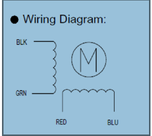
I have attached the wiring diagram that is for the stepper I am using. Can someone help me confirm which color wires are 1A, 1B, 2A, and 2B are for this motor?
One valid connection would be black and green wires to 1A and 1B, and red and blue wires to 2A and 2B. If you’re still having trouble, can you list all of your connections and post a picture of your setup?
Unfortunately that is the configuration I was using. Sorry I do not have a way of taking a picture
GND–>GND
5V–>Vdd(right next to(below))
Vdd–>5V (right next to(above))
3v3–>GND
GND–>GND
EN–>GND
MS1–>GND
MS2–>GND
MS3–>GND
RST–>SLP
SLP–>RST
STEP -->GND
DIR–> GND
Vmot -->+15V
GND --> GND
2B --> Blue motor wire
2A–>Red
1A --> Black (I tried switching the Black and green)
1B–> Green
Vdd–> 5V
GND–> GND
The 3V3 pin is the output of a 3.3V regulator, and you are shorting that to ground. This could explain why things are getting hot, and it’s possible you have permanently damaged the board by doing this. Can you just try making the minimum connections shown on the product page and see what happens?
first a thank you for a nice tutorial, i was able to get my steppers up and running in no time
i want to check if i did my math right setting the current limits.
my power supply is 12V (an old atx computer PSU)
from the motor i found that it requires 8,7V and 1A. So the correct limit for this motor would be ~=0.5A (8.7V/12V * 1A * 0.7)
i’ve tested with some other steppers as well and they seem to work fine by using this formula.
the problem that i seem to have is with selecting different microstepping mode(s).
the first wierd thing is when i don’t connect pins MS1, MS2 and MS3 i seem to get a quarter step mode (200 step motor takes 800 steps to make a full revolution). so it seems like MS2 is high (which is wierd since it says in the documentation that it has a pulldown resistor)
i tried to get other microsteping modes by connecting my 3.3V (from chipkit uno board) to MS pins (by using a 100k resistor … 3.3V ---->100k R ---->jumper---->MSpin) but nothing changed when i plugged the jumpers on MS1 and MS3, but when i connected the MS2 it went to full step mode.
My guess is that i should do it without resistors (or with much smaller resistors?)? But i didn’t want to try random ideas since i don’t want to damage the board in any way.
I don’t understand where this calculation comes from. The rated voltage of the stepper motor is not relevant when setting the current limit, nor is the voltage you are supplying. If you want to set the current limit to 1 A, you can put an ammeter in series with one of your motor’s coils (while in full-step mode with the step pin held fixed) and turn the trimpot until you see a current of 0.7 A (since the driver limits the coil current to 70% of the current limit setting in full-step mode). Alternatively, you can turn the pot to set the voltage on the “ref” pin to 0.4 V, which corresponds to a current limit of 1 A (assuming you have a board we manufactured and not a clone). In general, the relationship between the current limit and the reference voltage on our boards is given by:
current limit = ref voltage * 2.5
Did you buy your board from us? Can you measure the voltage on MS2 and see if it really is high? You don’t need to use resistors between your logic voltage and the driver inputs; if you do use resistors, you should use much smaller ones as 100k is not going to be strong enough relative to the various pull-downs already on the board or inside the A4988 IC.
After some more reading i tried to do the folowing:
rewire the pins MS1-MS3 so that i have a connection from 3 OUTPUT pins on my chipkit and reading 3buttons and if i read HIGH on the button (pressed) then use digitalWrite(MSpin, HIGH) and if the button is not pressed then i write LOW. (with no resistors this time)
and as wierd as this sounds, i can only get the motor running in full step or quarter step.
only the button connected to pin MS2 has the desired effect.
I’ve checked the button wiring and as debug i output the values of buttons pressed or not and the buttons are fine.
any ideas?
as for the current limiting, my thought proces went in a way that i should keep the current lower since the voltage is higher and keep the power in balance, example…
i have a motor rated 3,9V and 0.6A P=U*I gives me 2,34W in order to have the same power with 12V the current should be 195mA and 70% of this is 136mA (and i thought that that is the value i should read from my ammeter.
i use this boards: pololu.com/catalog/product/1182 so i don’t have a ref pin i can access but i tried to set up the current higher (for the motor with 3,9V and 0,6A that would be 0,42A) and the motor gets rather warm, is that normal?
EDIT: things just went from wierd to bizzare… i went checking if i might have made some errors while soldering and if there is a short circut somewhere or some other abnormality, didn’t find anything, but as i gave it another go, the damn thing started to work (i also tried it with another A4988 driver and it worked fine, and then with the first one again and it worked as well)
when things are not working and you don’t know why its strange, but when they suddenly start to work for no apparent reason its even worse (cause i’m afraid they will stop again).
Another question/idea. Could it by any chance be that the problem comes from me not using any capacitors on the vcc and vmot lines? considering the power suply comes from an atx power supply that should be relatively stable (and im guessing the same about the chipkit’s 3.3V line)?
The important rating to avoid exceeding with a stepper motor is its current rating, and that is what you accomplish by setting the current limit.
The ref pin voltage is available through the untented via near the sleep pin. This via is circled on the bottom silkscreen.
Yes, the coils have a resistance that dissipates power as heat, so as the current goes up, they will get warmer. As long as the current doesn’t exceed what the motor is rated for, however, the stepper motor should be fine.
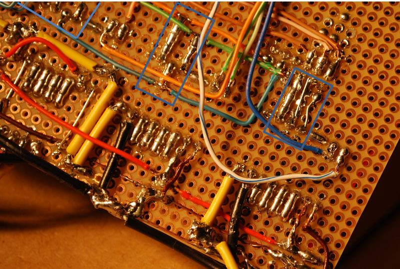
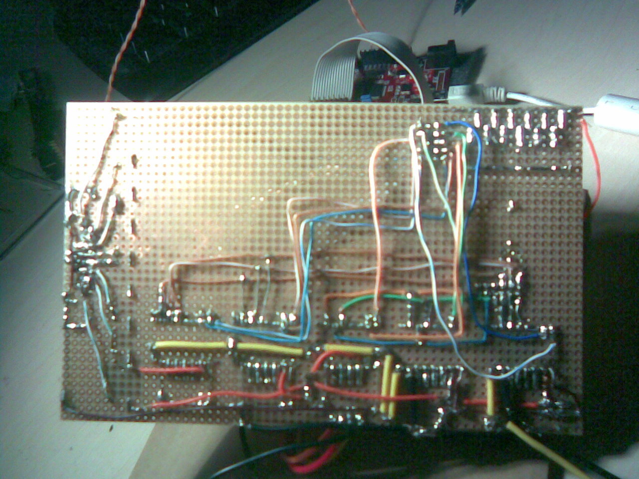
Your problems sound like the MS1 and MS3 pins are making intermittent/poor connections, which makes me suspect your soldering job. Can you post a picture of your board that would let me evaluate the quality of your soldering? Also, if you are using a power supply with leads longer than a few inches, I suggest you put a large electrolytic capacitor across VMOT and GND somewhere near the board to help protect it against LC voltage spikes. Please see the warning box under the Power Connections section of our A4988 product page for more information.
Ok. thnx for clearing that out for me, guess i was confused by the motors getting warm/hot and thought i should change the equation to get a smaller current limit… And you are right, there is this ref pin and i stand corrected. silly me.
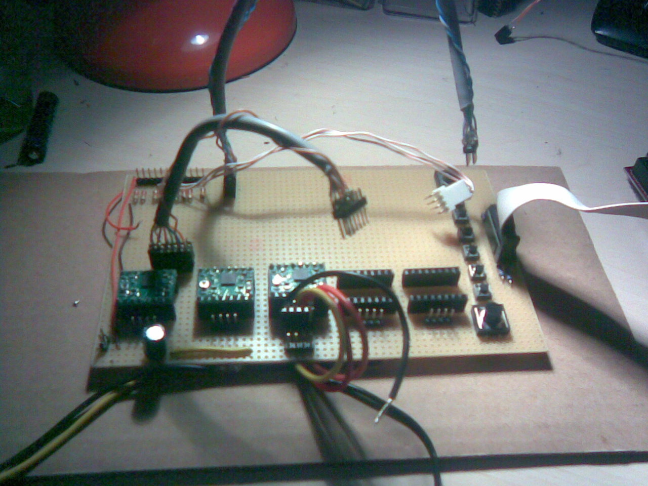
Attached you can find the picture, i have marked the MS pins, but now it’s working as it should. I hope my soldering is not horrible, it’s my first non breadbord project and i’m still learning. If you see something i’m doing wrong please tell me so i can improve. Also i’ve had a 100uF capacitor lying arround so i soldered that in as well, between VMOT and GND.
I don’t see any obvious problems, but only your first picture in focus enough for me to see what’s happening, and even that one is too far away for me to really be able to determine if there are any unintentional shorts or cold solder joints. In general, you have a lot of connections that you’ve made yourself, so you might need to touch some of those up if you run into apparent connection problems. If you really want to be confident that it’s a connection issue, you can swap a different driver into the same socket and see if the problem persists. That would imply either a problem with the socket connections or with your code. If the problem follows the driver, then it could be an issue with the soldering of the header pins to the driver, or the driver could be damaged in some way.
If you are relatively new to soldering, I recommend you check out some of the free online soldering tutorials available so that you know what your solder joints should look like. Adding too much or too little solder can cause problems, and using the wrong technique can result in blobs of solder that don’t actually make the electrical connections you think they are.
Hi everybody!
Really helpful the guide to start with.Thanks for all the guidance.I got only one question about the A4988.I accidentally connected 5V to MS1 while it was driving a stepper motor and from then on I got no current to the coils and no reaction at all from the module.I use an arduino-one to control it.Is there a possibility that it’s “locked” or shall i face it that i did something stupid?
It sounds like the driver has been damaged, though connecting 5 V to the inputs should be fine. Are you sure it was 5V? Can you describe in more detail exactly what you were doing when the driver stopped working? Note that changing connections on a device like this while it is powered is generally a bad idea.
I am working on an Arduino project board to launch rockets. On my last board, which is no longer with us RIP, I was using a different stepper motor driver but I want to upgrade to the A4988. I want to make the board so that it can be used for other projects and want to be able to select the different levels of stepping. I understand that three switches or jumpers can be used to tie MS1, MS2, and MS3 to ground. Question is, would I want the other connection on the switch to go to 5 v or no contact.
A second question, I am using a stepper motor to “open a lid” for the rocket to fly out of. I understand that 9v batteries aren’t very good for powering stepper motors. I found one 9v will be dead in about 4 minutes of the coils being charged. That being said, they fit very nice in my project and the motor coils are only charged for about 25 seconds total leaving two 9v’s plenty of power to do their job. On my last board, I had a relay between VMOT and +9v so the battery would not discharge while the system was idle. When the launch sequence was initiated the VMOT was powered, motors did their part, and then power was cut to the motor driver board. The motor driver I was using didn’t have an enable pin. Question is, will the enable pin on the A4988 keep the motor’s batteries from discharging allowing me to get rid of the relay? If the lid don’t open I’m kinda screwed…
The microstep selection pins are pulled low by default, so you would probably want to use a switch that toggles between high (5V) and open (no contact).
The enable pin will turn off the stepper motor driver outputs, so you should be fine to get rid of the relay. However, I am concerned that a 9V battery might work poorly for your application for reasons other than its quick discharge time. In general, 9V batteries cannot deliver much current, and when you try to draw more than they can deliver, the voltage drops, potentially by quite a bit. The minimum motor voltage for the A4988 drivers is 8V, which is not much higher than your battery’s nominal voltage, and which your battery might drop below rather quickly as it discharges. You mentioned using two 9V batteries; I am not sure how you have them connected, but you might consider using them in series to supply the driver with 18V. Also, I suggest you set the driver’s current limit to be the lowest current you need for your application.
Please note that we do not recommend our products for applications where failure can lead to injury or destruction of property. I strongly suggest you build some kind of failsafe into your design to keep the rocket from launching if the lid is not open.