I am trying to run a 12V motor using a drv8835 driver. It all works fine on an Arduino Uno but with my project I am using an a-star 328PB 8Mhz 3.3V board. When I connect it all up and drive 5V power from my mains power supply to the driver, the motor works fine. When I connect it to 2 output pins from the a-star board, every SINGLE time I try to output a high to the driver board ot run the motor it resets. I can’t figure out why and it’s been killing me for hours. 
I have tried connecting the board to a couple of different digital pins, and currently have it connected to pins 6 and 7. I am not sure what I am doing wrong and would love any advice.
Hello.
Could you post more details about your setup, including pictures showing all of your connections and the code your A-Star 328PB is running? Also, what power supply and motor are you using, and how are you powering the A-Star?
Brandon
1 Like
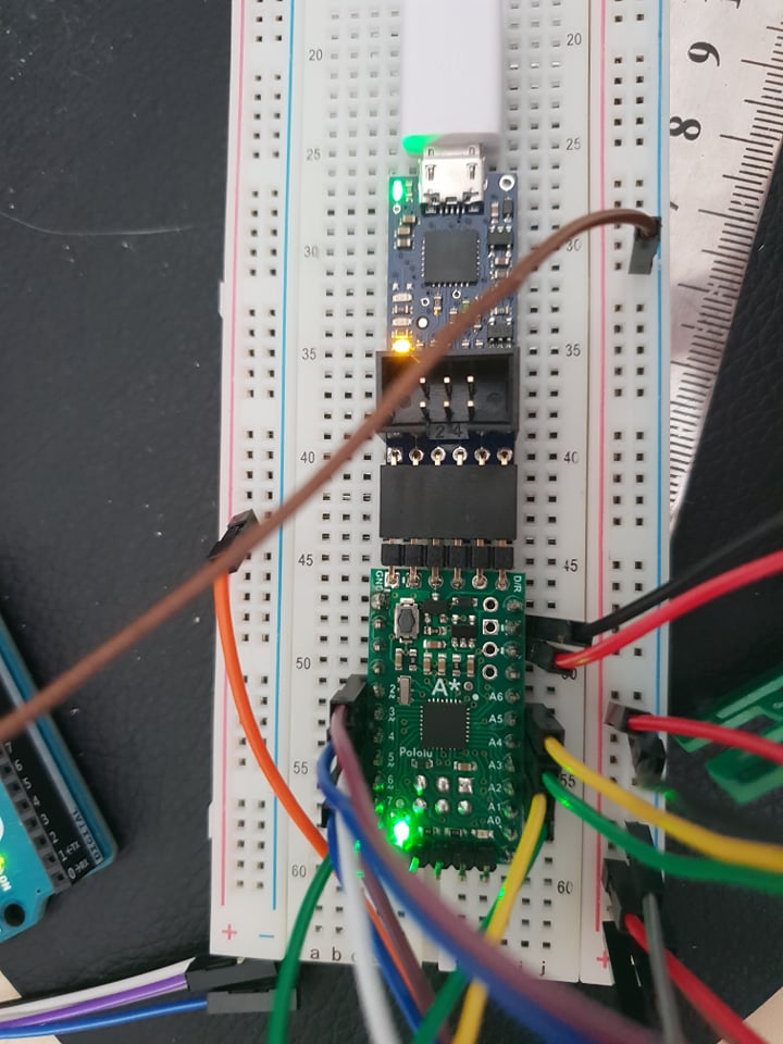
Hey, attached is an image of the setup. I have a few other working sensors attached to it, but the motor phase and enable pins are attached to Pins 2 and 3 on the A-star. I have gotten it working when I connect the 5V power source directly to the contorller, so I know it all works fine (as it did when I was running everything on the Arduino Uno), but it still resets everytime, but atleast this time runs (but resets and keeps running over and over again).
This is teh motor I am using. I am just not’ sure what the issue is currently. https://www.amazon.com/Alltronics-FK-130SH-Mabuchi-RC-Motor/dp/B014DX2J8K
Here is the code:
const int m_enable = 2;      // the number of the m_enable pin
const int m_phase = 3;      // the number of the m_phase pin

void setup() {
  // put your setup code here, to run once:
  pinMode(m_enable, OUTPUT);
  pinMode(m_phase, OUTPUT);

  Serial.begin(9600);
  Serial.println("Setup complete...");
  Serial.println();

  delay(1000);

}

void loop() {
  // put your main code here, to run repeatedly:
  digitalWrite(m_phase, HIGH);
    digitalWrite(m_enable, LOW);
}
Thank you for the additional information. Could you post pictures of your full setup, including the DRV8835 carrier and all of those connections? What are you using to supply power to the driver?
Brandon
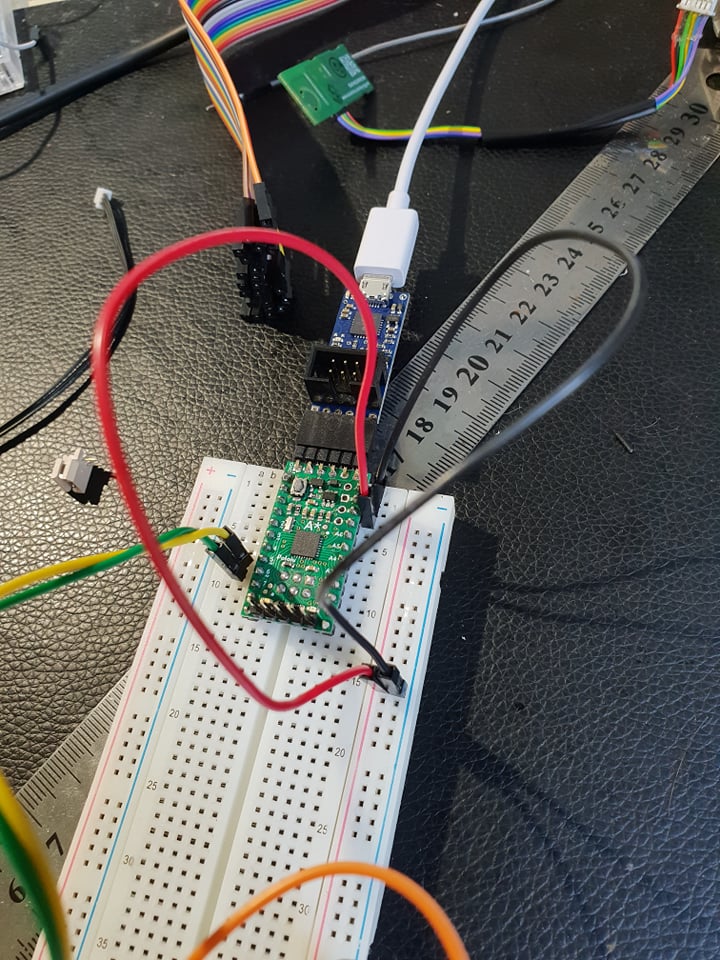
Hey, sorry I just broke it all down and removed everything else trying to get it working. But it still didn’t work. Below are the images of my setup and teh steps I have done to get it working.
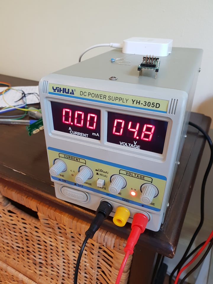
- I have plugged the motor directly into the power supply and it works fine.
- I connected the motor to the drv8835 (I believe orpoerly) and hav checked all the voltages at different pins and all the pins that should have voltage have voltage but no motor running. The inputs to the motor driver I connected directly to the power source at 5V input, but that didn’t work.
- I did step 2 but with the driver input from the a-star and it also didn’t work.
Hey, I have an a-star 3.3v microcontroller (https://www.pololu.com/product/3162) and I am currently setting it up with no issues. But I have noticed the output of the digital pins is 5V. I am currently powering it with an external 5V power supply into the Vcc pins. Can you tell me why the IO pins have a logic voltage of 5V, I thought they should have been 3.3V or am I missing something obvious? Thanks and sorry for the silly questions.
An update I have found. The 5V was under no load, but when I put an led on a digital pin it only outputs 2.5V, which is barely enough to turn the LED on. Any suggestions on why this is happening and what I am doing wrong?
Thank you for the additional information and pictures. I have combined your new thread with this one since they seem to be about the same setup, and it could be a related problem.
Please note that the A-Star 328PB is intended to be powered through the BAT+ pin. VCC is the logic level output, so you should not be applying 4.8V to it. This is probably causing the odd problems you are describing with the digital output not being 3.3V. After you correct that, could you test your A-Star pins with your multimeter to verify that are working as expected before connecting them to your driver again?
For the DRV8835 driver, since you are using 3.3V signals, you should apply 3.3V to the VCC pin. Also, it sounds like you are intending to use the driver in the PHASE/ENABLE control mode, so to do that you should pull the mode pin (MD) high, you can either do this with a pull-up resistor to VCC or by driving it high from an I/O line from the A-Star.
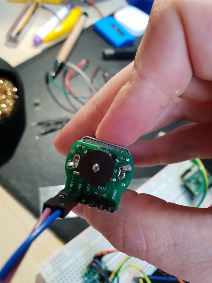
Along with those changes, I also suggest testing your motor separately from the rest of the setup if you haven’t done so since your system started having problems. You can do this by powering it directly from your supply and making sure it is not stalled or drawing more current than expected. Sometimes encoder discs can be pushed on too far and rub against the PCB components, which can easily cause the motor to stall.
Brandon
Hey, thanks. I have tried to power my a-star through the battery and it has seemed to fix the output voltage issue. I have also figured out why teh drv8835 driver wasn’t working. I had the motor and pins all connected ot the “B” section of the driver and it didn’t work. Once I connected it to the “A” section it all started working fine. So I am not sure hwat the issue was there, it was a brand new driver I was using too, with no shorts as far as I could see.
I am glad to hear that those changes helped. Just to clarify, are you saying that switching from the DRV8835’s B motor channel to the A motor channel got your motor running, but the B channel on the driver still does not work correctly?
Brandon
Hey Brandon, yes that’s right. I do not know why since it is a brand new driver. But it works now.