
The pinout chart for the 328PB shows pins 0 & 1 can be used as PWM (analogWrite) although they are typically part of TTL programming. I want to use these 2 pins for fading LEDs but unless I can disable RX/TX on them it doesn’t work. How do I do that? I’m already using analogWrite on pins 2, 3, 5 & 6 so I’m out of PWM outputs unless I try pins 10 & 11 on the bottom of the board as I need a total of 6 PWM/analogWrite pins. I had a look at the datasheet but couldn’t see what I need.
Hello.
You did not say whether you are programming the A-Star 328PB via its ISP header or via the TTL serial programming header.
I would recommend using the ISP header so you do not have to worry about pins 0 and 1 being used by the bootloader and by the USB-to-serial adapter. If you do that, the AVR’s UART should be disabled by default and you do not have to do anything special to disable it.
–David
I’m programming the board via TTL using the TTL port. I have not wanted to use the ISP header as it blows away the bootloader.
Are you saying that if I program the board via the ISP header it will disable the TX/RX on those pins? Because I tried setting them both to OUTPUTs in my setup() to no avail.
The USART, which provides TX and RX functionality, is disabled by default. However, the serial bootloader that we provide for the A-Star 328PB enables it in some circumstances before your program runs. If you program using the ISP interface, you would erase the bootloader, meaning that the USART would always be disabled by default.
If you want to use the bootloader instead of ISP, you should be able to disable the USART at the beginning of your program with this line of C/C++ code:
UCSR0B = 0;
–David
Excellent, thanks so much David!
I got pin 1 to work when programming the 328PB board via ISP, STK500 for 328PB and the programming port using Sketch>Upload using Programmer, but still nothing out of pin 0 (regardless of adding UCSROB = 0;)
Code
/*

Constant Speed 4-wire stepper motor control using AccelStepper library
======================================================================

Copyright (c) 2019 Ross A. Waddell

Sketch is for personal use only.


To program:

  Board       -> "A-Star 328PB" (https://www.pololu.com/product/3160)
  Port        -> "/dev/cu.usbmodem002795022" (ISP programming port)
  Programmer  -> "STK500 for Pololu A-Star 328PB"

>> This Pololu board needs to be integrated with the Arduino IDE for use. See chapter 4
>> https://www.pololu.com/docs/0J74

  Nothing can be connected to any of the TX/RX PWM pins (if they're being used) while programming or it won't work.
  Best thing to do would be to program the board separately, so use male headers so it can be popped in and out.

  * Connect Pololu AVR Programmer to 2x3 ISP header
  * Set Regulator mode to "5V"
  * Set VCC output to "Enabled"
  * If using PWM pins 10 & 11, need to disconnect wires to LEDs before programming
  * Choose "Sketch>Upload using Programmer"


TODOs
=====

  1.


*/


// Comment out the line below for production
// (serial monitoring affects timings)
//#define DEVMODE

// Libraries
// =========
#include <LEDFader.h>     // https://github.com/jgillick/arduino-LEDFader
#include <Curve.h>
#include <jled.h>         // https://github.com/jandelgado/jled


// Running lights and Strobe lights LED setup
// ******************************************

/*

  1.  Running Lights (top/bottom of saucer section, port/starboard):

      * Timings taken from opening scene in "Th Tholian Web"
      * Approx. 1-1/2 sec (36 frames) on, 1/2 sec (12 frames) off

        ' Alternate is 1/2 sec on, 1.5 sec off (reverse of above).
        ' In "The Corbomite Maneuver", the lights were on for 18 frames and off for 20
        ' For the 2nd pilot, the lights were on for 1 sec and off for 2/3 sec (Trek Ace)
        ' (http://www.hobbytalk.com/bbs1/showpost.php?p=4515070&postcount=10)

  2.  Formation/Strobe Lights

      * Timings taken from the third season special effects shots ("Star Trek Original Series Enterprise Reference Shots (Doug Drexler).mp4", approx. 05:35 mark with Enterprise firing phasers)
      * Approx. 3/24 seconds on (125ms), 8/24 seconds off (333ms)

 */


// 1.  Running Lights (top/bottom of saucer section, port/starboard):

#define LED_RUN_LTS_PIN 0
boolean ledRunLtsState        = HIGH;
const int MAX_BRIGHTNESS      = 255;

const int FADE_TIME_RUN_LTS   = 125;
const int LED_RUN_LTS_OFF_DUR = 500;                          // Time off in milliseconds
const int LED_RUN_LTS_ON      = 1500;                         // Time on in milliseconds
// This takes into account the fade in/down time
const int LED_RUN_LTS_ON_DUR  = (LED_RUN_LTS_ON - FADE_TIME_RUN_LTS*2);

LEDFader ledRunLts;

// 2.  Formation/Strobe Lights

#define LED_STB_LTS_PIN 1

const int LED_STB_LTS_OFF     = 333;                          // Time off in milliseconds
const int LED_STB_LTS_ON      = 125;                          // Time on in milliseconds

auto led_strb_lts = JLed(LED_STB_LTS_PIN).Blink(LED_STB_LTS_ON, LED_STB_LTS_OFF).Forever();


void setup()
{

  //UCSR0B = 0;   // Needed when using pin 1 for PWM

  ledRunLts = LEDFader(LED_RUN_LTS_PIN);
  ledRunLts.set_curve(&Curve::exponential);
  ledRunLts.fade(MAX_BRIGHTNESS,FADE_TIME_RUN_LTS);

}


void loop()
{

  unsigned long ms = millis();                // Get current time in milliseconds (for LEDs)

  ledRunLts.update();
  blinkLED_Run_Lts(ms);                       // Call function to blink running lights

  led_strb_lts.Update();

}

// FUNCTIONS
// ---------

void blinkLED_Run_Lts(unsigned long currentTime)
{
/*

  Function has parameter (unsigned long currentTime) to determine if it's now time to blink on or off the LED.

  In this case, rather than simply turn on or off the LED a fade is initiated using LEDFader. But, LED will not
  turn off or on again until the specified time has elapsed.

  Returns: nothing

*/

  static unsigned long msLast1;

  if (currentTime - msLast1 >= (ledRunLtsState ? LED_RUN_LTS_ON_DUR : LED_RUN_LTS_OFF_DUR)) {
      ledRunLtsState = !ledRunLtsState;

      if(ledRunLtsState == HIGH)
      {
        // Fade up
        ledRunLts.fade(255, FADE_TIME_RUN_LTS);
      }
      else
      {
        // Fade down
        ledRunLts.fade(0, FADE_TIME_RUN_LTS);
      }

      msLast1 = currentTime;
  }
}
Setup
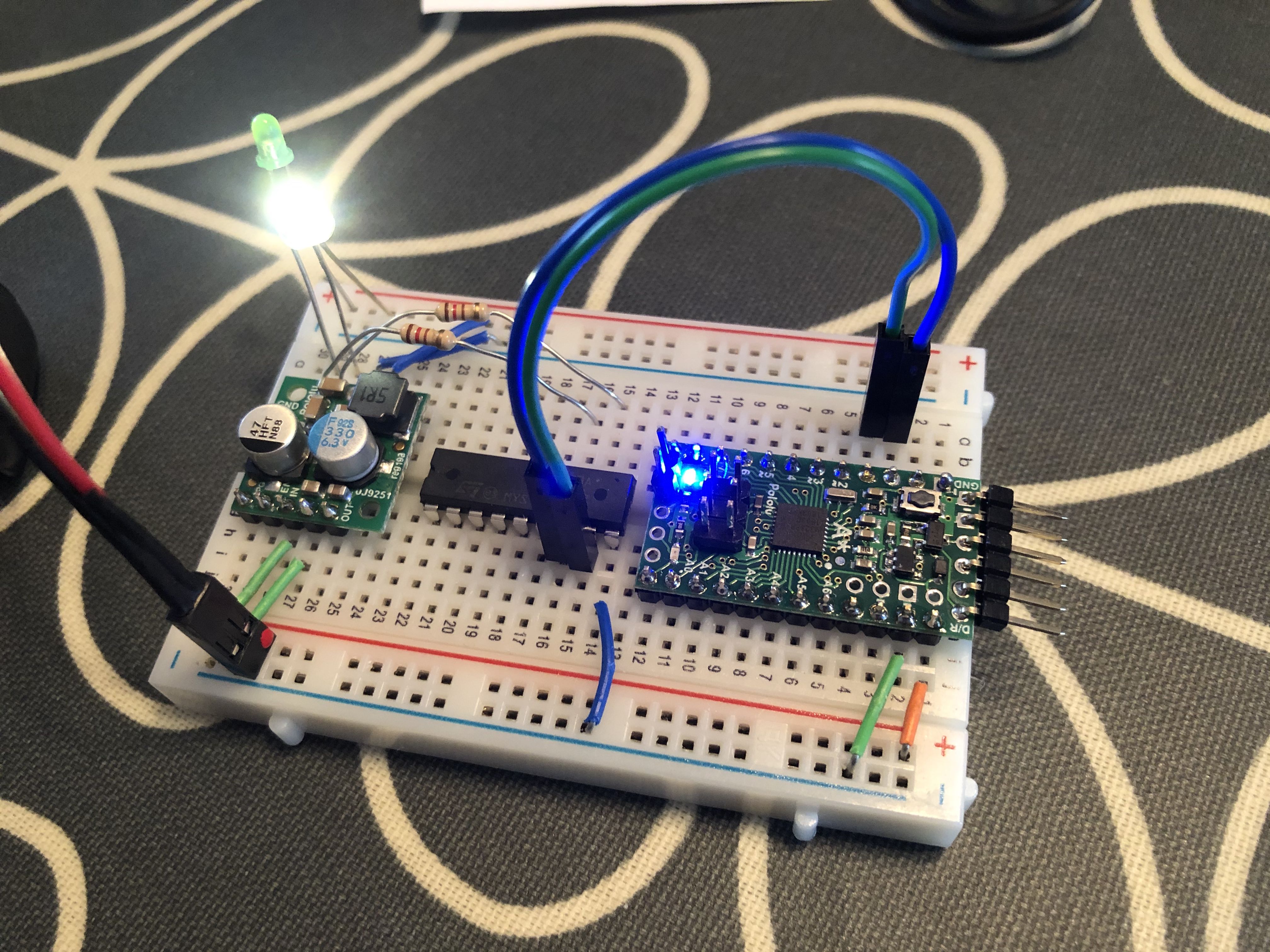
I just tried the basic blink program and it works on pin 0, so the problem must be with using PWM on it:
void setup() {
  // initialize digital pin LED_BUILTIN as an output.
  pinMode(0, OUTPUT);
}

// the loop function runs over and over again forever
void loop() {
  digitalWrite(0, HIGH);   // turn the LED on (HIGH is the voltage level)
  delay(1000);                       // wait for a second
  digitalWrite(0, LOW);    // turn the LED off by making the voltage LOW
  delay(1000);                       // wait for a second
}
I’ve had similar problems with using PWM on pin 2.
EDIT: I don’t think this has anything to do with the 328PB, but rather the LED fading library I’m using. My guess is that their code doesn’t recognize pin 0 as PWM-enabled.
You might consider using analogWrite on pin 0. I expect that to work.
–David