
For two years I’ve been working on a small maze solving robot. I started with McCabe’s design from 2011.
Robot size is 9cm x 8.5cm. It successfully completes a maze, without loops, 100% of the time. It also makes a second optimized run. The maze is based on a 6 inch grid using 3/4th inch wide electrical tape. All junctions are at right angles.
This is not the end of the project. I’m now experimenting with ‘breadth first’ and ‘depth first’ tree search techniques working toward loop maze solving algorithms.
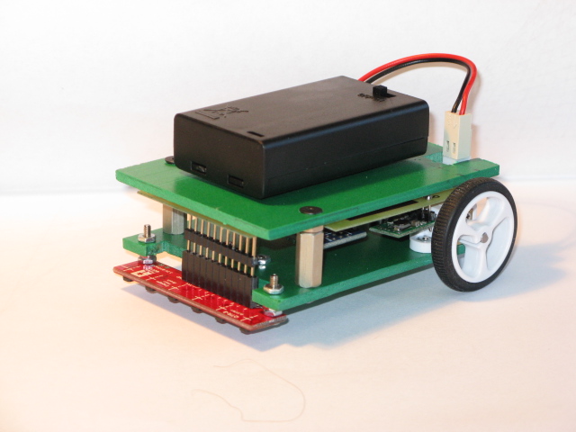
All the main components, except for the Adruino Nano, were purchased from Pololu: To ensure steady power the #2562 regulator ensures a steady 5 volts to the robot, even as battery power wanes. The motors are driven by the #2135 dual motor drivers. Power is provided by 3-AAA batteries from a switched box, #1147. It should work with a 2-AA box with switch, #1160.
Motors are #1097, 90 RPM, with #1088 wheels. Motor brackets are #1089. The robot must be made wider if you want to add motors with encoders. The ball caster is #950.
Maze sensing is performed using four of six sensors on a #960 sensor unit. Two center sensors follow the line and two outer sensors search for junctions. These sensors provide analog output that makes for simple line centering using only proportional error control. These sensors have 3/8th inch sensor spacing. I prefer this pitch to the black sensor 8 mm pitch for two sensor line centering.
The robot was designed going back to first principles. The Arduino IDE was used for programming with no include files, or libraries. After years of experimenting with large “floor sized” robots I selected this design to allow for table top sized mazes. But as robots get smaller parts tend to cost more.
I’m retired so my hobby is intended to fill free time. (If you are under time constraints a 3PI might be a better choice.) This is my third version of the bot. My first used a PIC microcontroller using assembler language. The last two versions used the Nano. Unseen in the photo are four LED’s, behind the battery, for program feedback.
If there is interest I will provide schematic, PCB layout and software. Two versions of software exist. In the first, all turns are made like a “zero turn” lawnmower. In the second version, left and right turns are made with stopped inner wheel as the radius center.